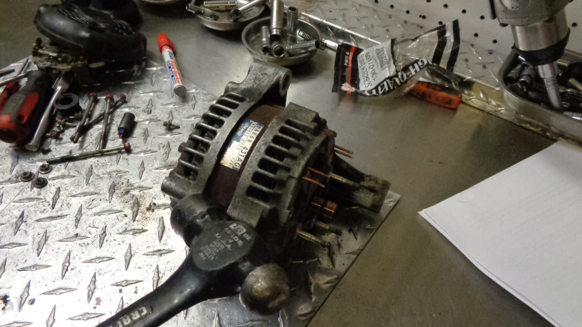
Chrysler, Dodge, Plymouth Mini Van Alternator 2001-2007 3.3L 3.8L
HOW TO REBUILD A 2001-2007 DODGE CARAVAN,PLYMOUTH VOYAGER, CHRYSLER TOWN & COUNTRY ALTERNATOR. MINI VAN WITH CLUTCH PULLEY.
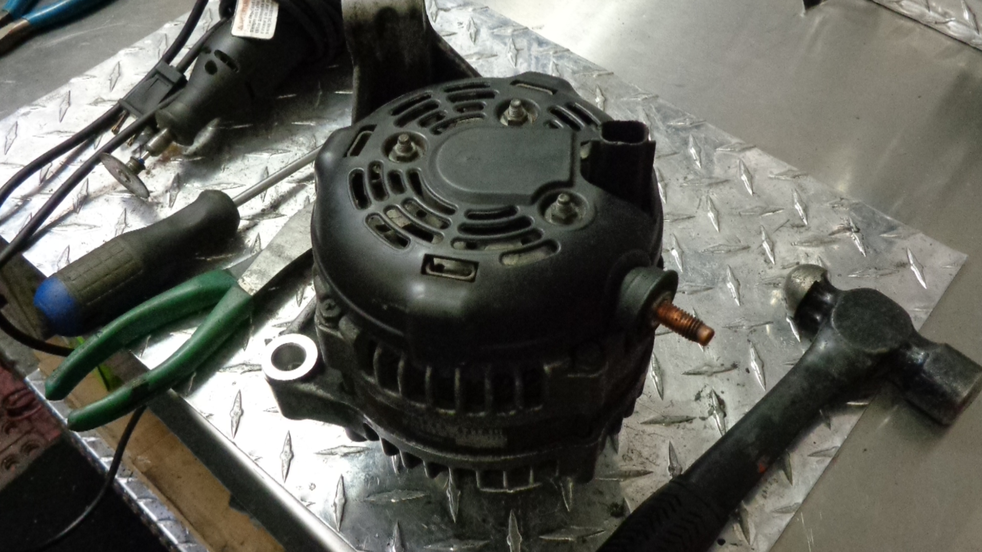
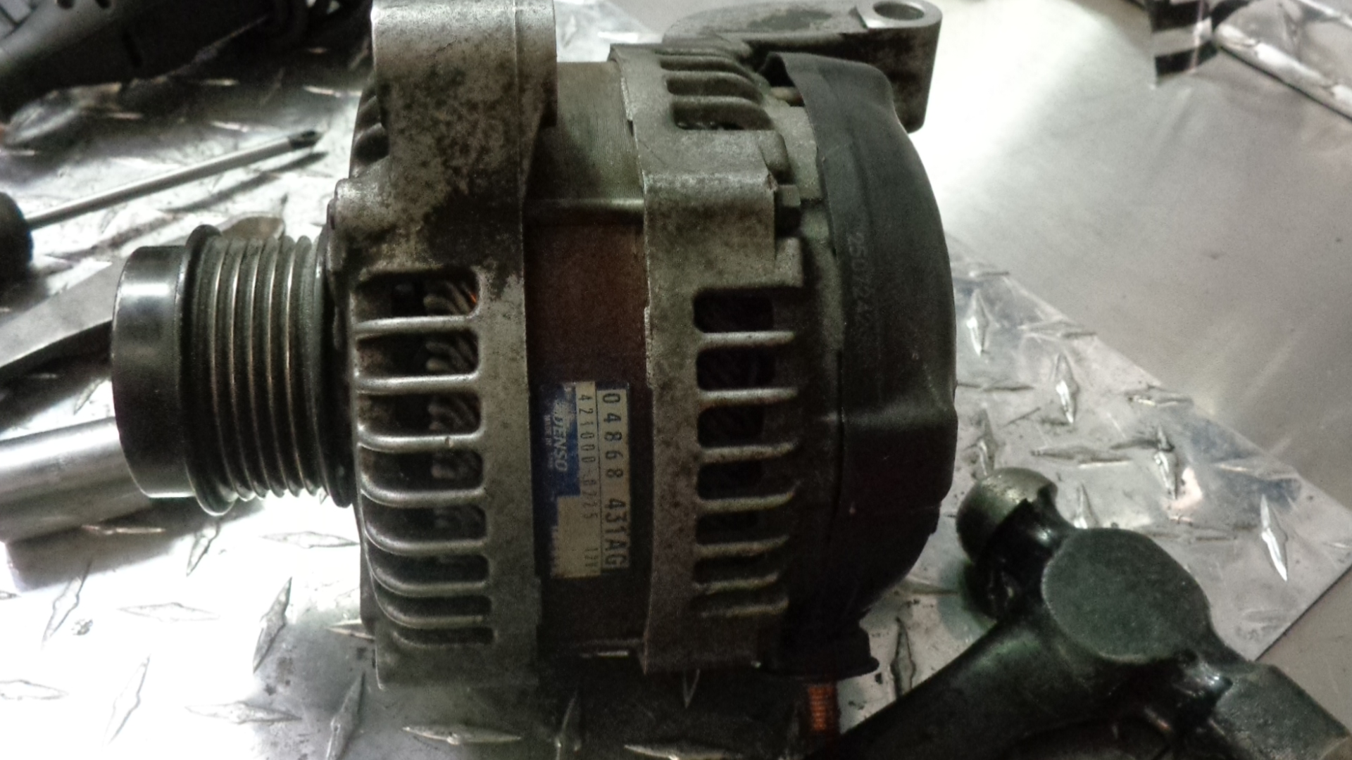 One of the most popular Denso high amp hair pin type alternators is on the Chrysler, Plymouth and Dodge mini van with a 3.3 or 3.8 litre engine from 2001 to 2007. The most recognizable feature of both the 160 amp, and the 136 amp models is the pulley. It is a new style of pulley that is referred to in the industry as a “clutch pulley” . We use the the same parts kit for both models. None of the Chrysler made mini van alternators have a built in voltage regulator. The voltage regulator is in the computer.
==================================================================================== 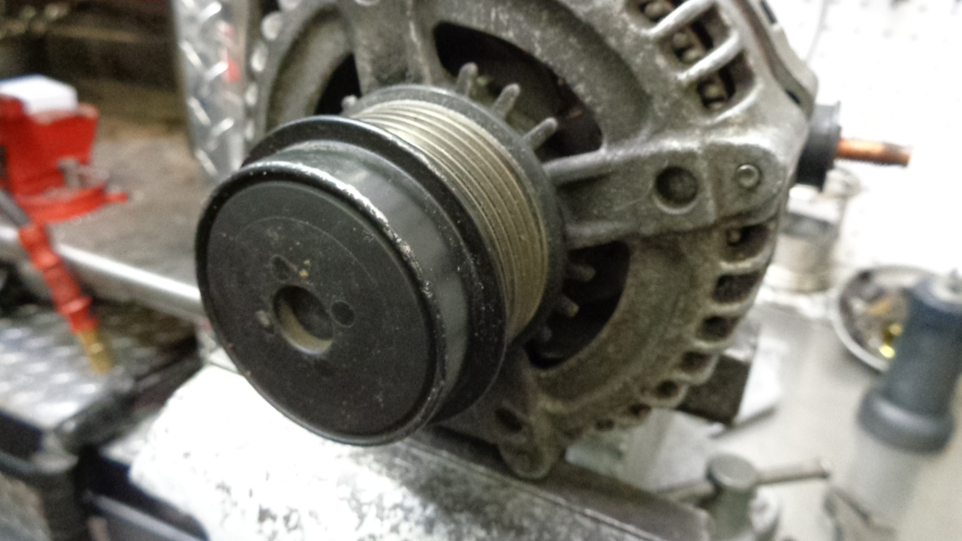
The pulley consists of 3 major components.
- An outer shell
- An inner shell which threads onto the alternator shaft.
- A heavy duty coil spring connecting the other 2 pieces.
- Included in the pulley, are centrifugal clutch assemblies to gradually engage and partially disengage the other components. Also, the assembly is centered with typical roller bearings.
The purpose of the clutch pulley is to create a gentle mechanical connection between the belt and the pulley, thereby extending belt life and alternator wear while dampening vibration.
===================================================================================================
THE REBUILD : wear eye protection at all times
PULLEY REMOVAL
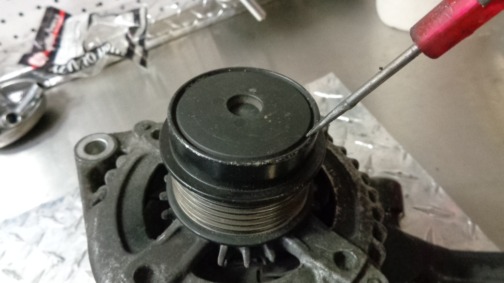
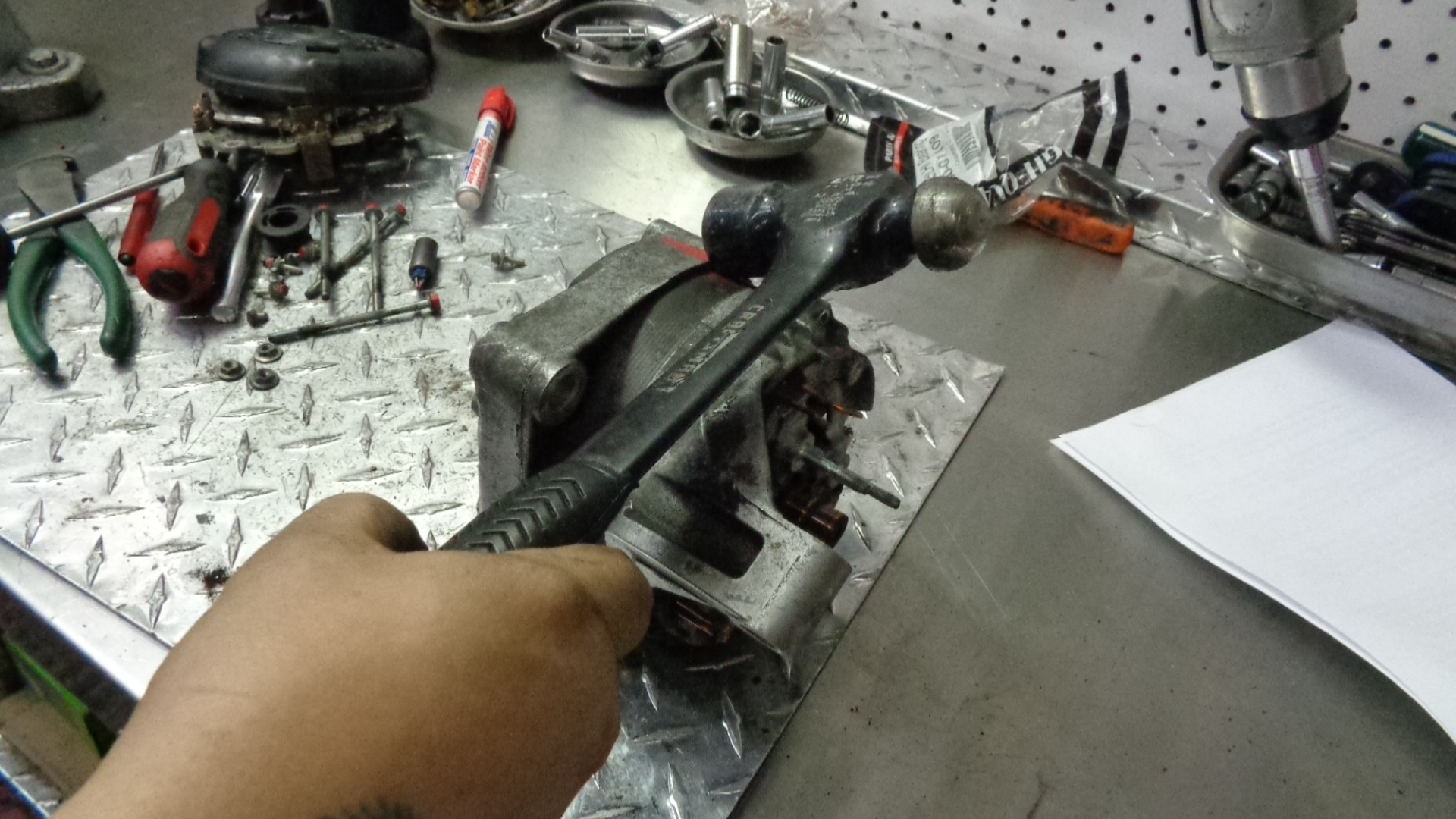
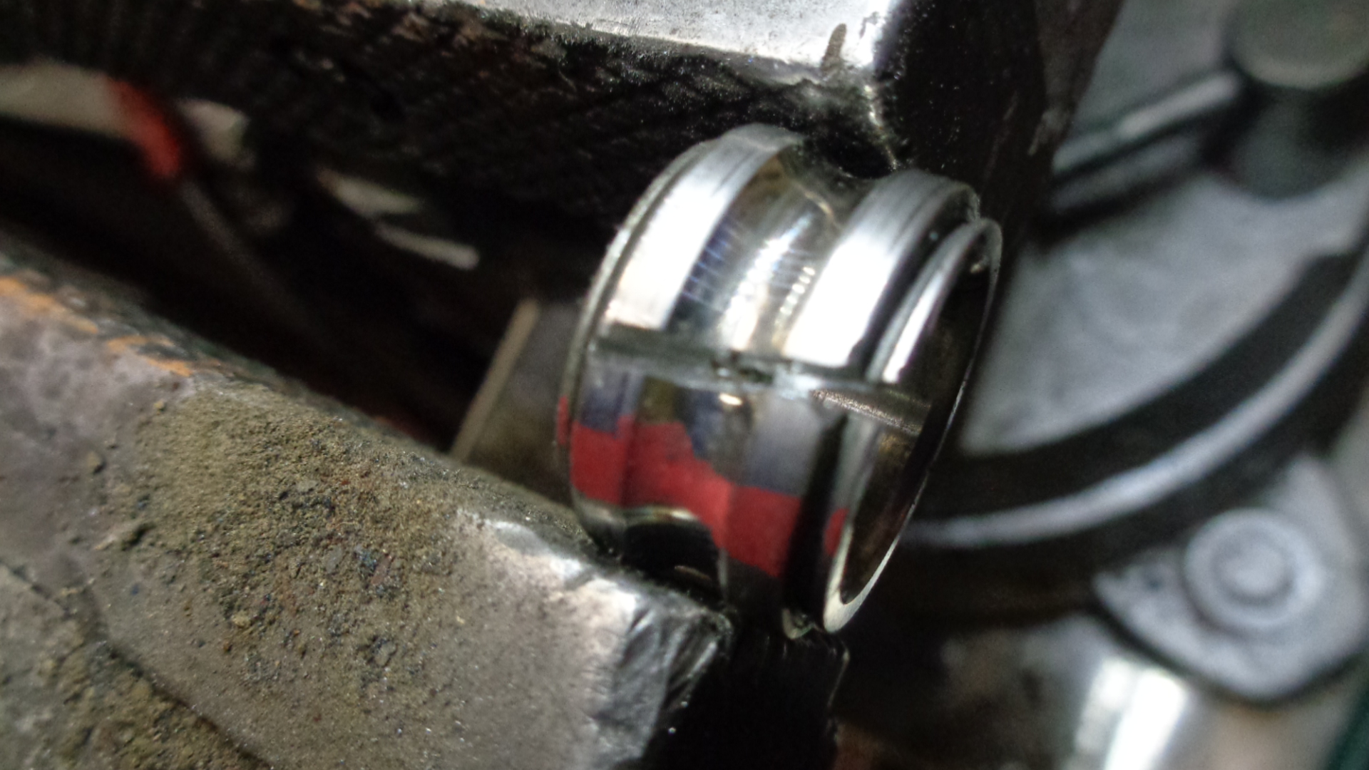
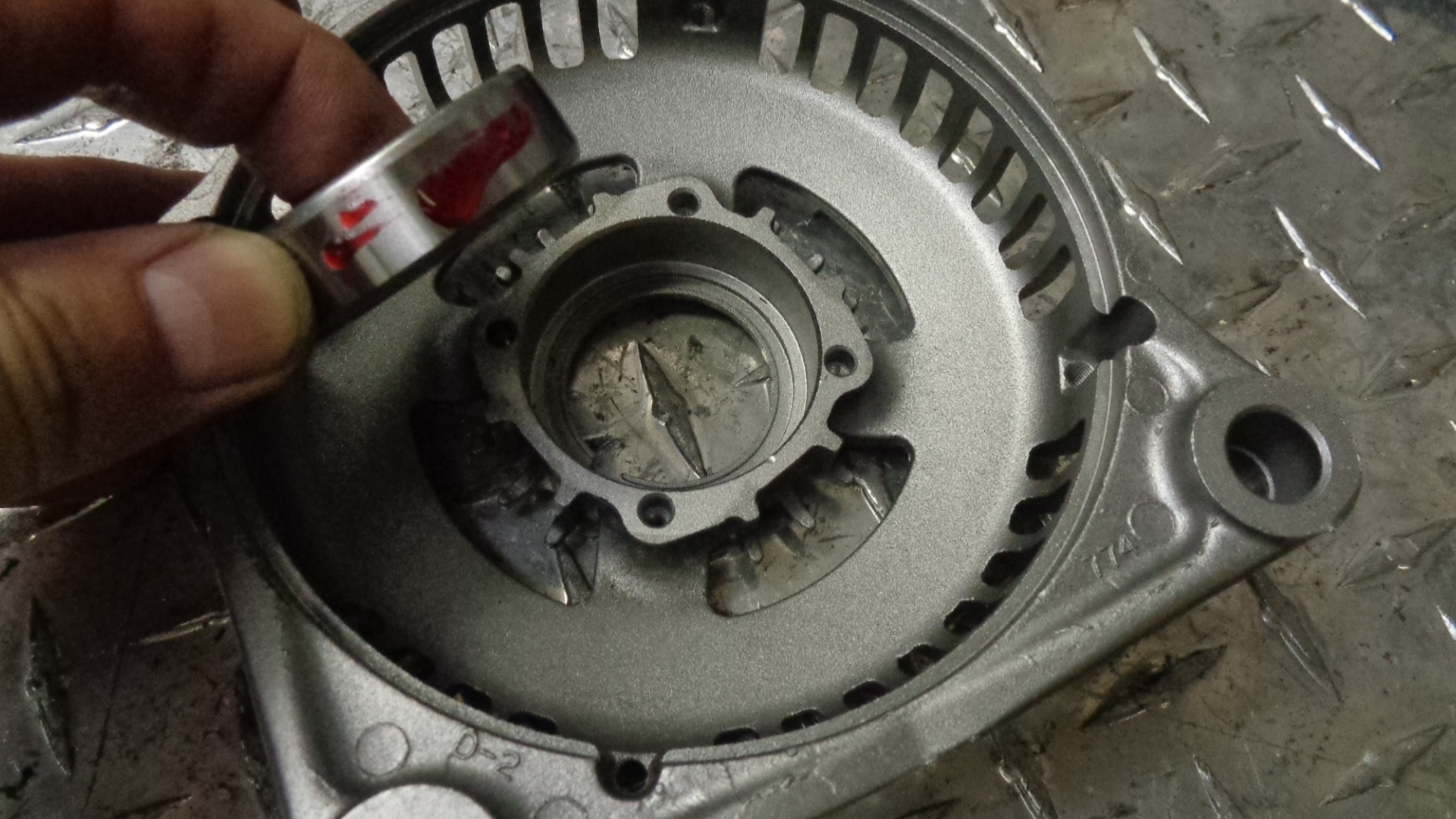
Turn the alternator on it’s back, plastic side down. With a hammer, pound down firmly on the black plastic flat area of the pulley cover. This will loosen the dust cover on the alternator to gain access to the 17mm allen area.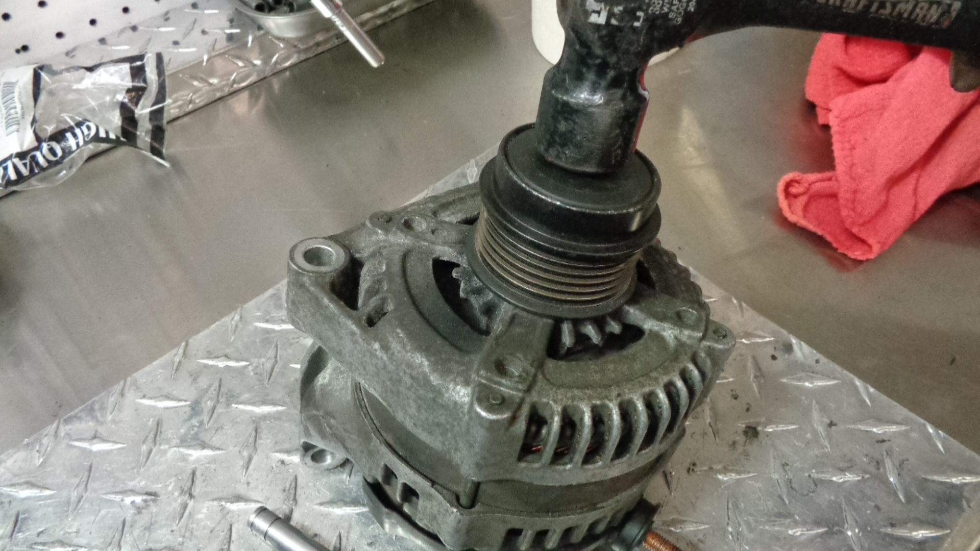
Use a pocket screwdriver to pry the plastic cover out of the way.
================================================================================================================
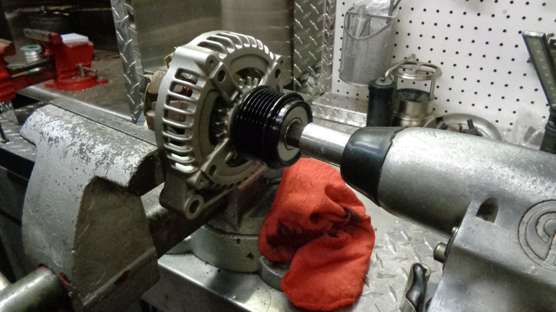
To remove the pulley from the shaft you will need a ½” drive impact gun set to reverse (L) and a 17mm allen. Hold the body of the alternator with one hand and apply a series of short bursts to the gun. (Electric or air will work). It is important to let the alt. shaft stop between bursts. Discard pulley (6 groove).

===============================================================================================================================
REMOVAL OF BRUSH AND TERMINAL BLOCK 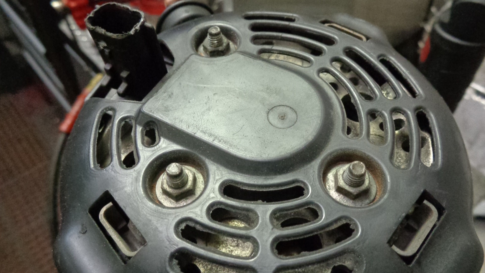
Remove the 3 nuts on the back of the alternator that hold on the black plastic cover. (5/16 socket or 8mm). After the 3 nuts have been removed, the black plastic cover comes right off.
============================================================================================================= 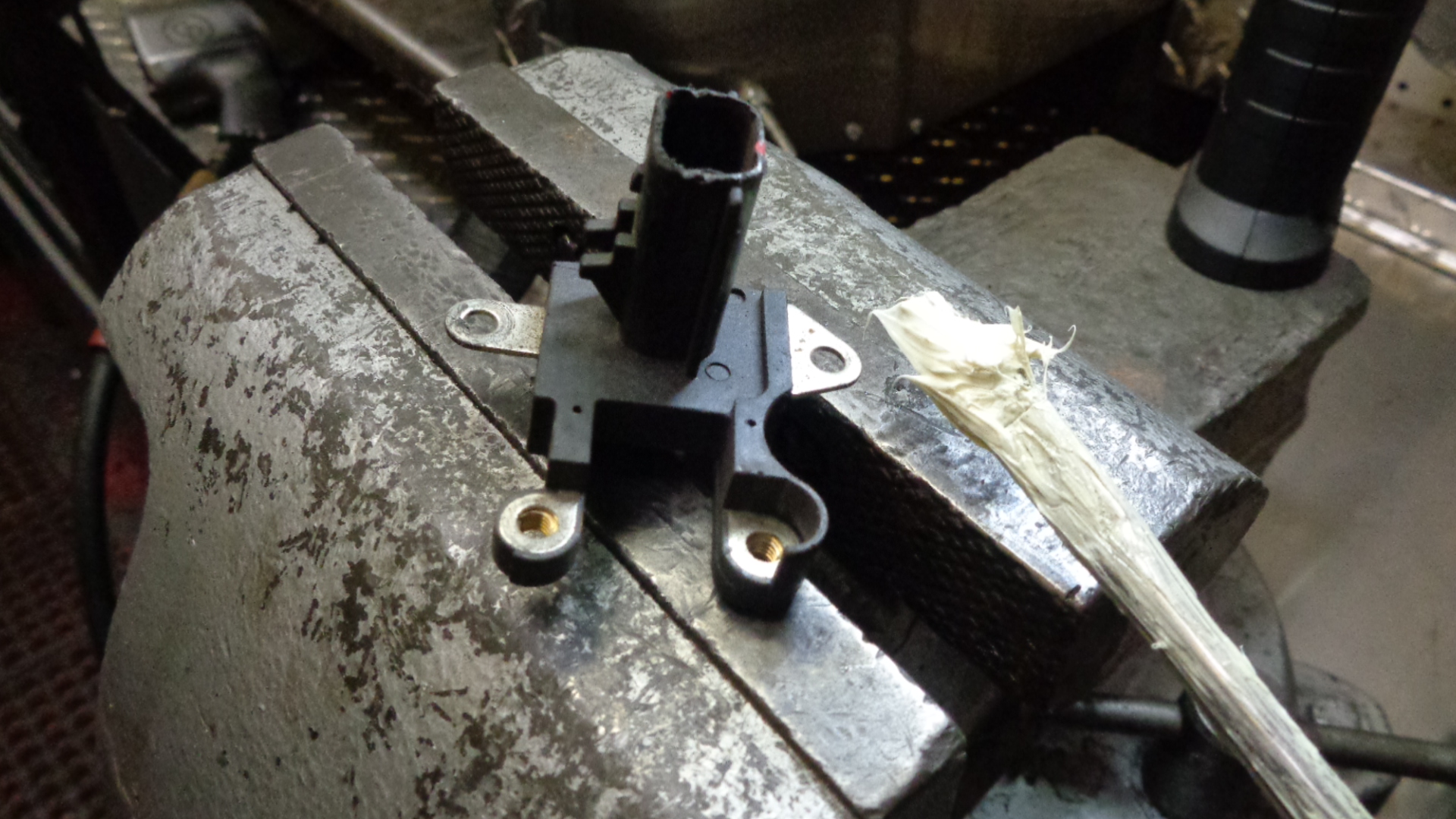
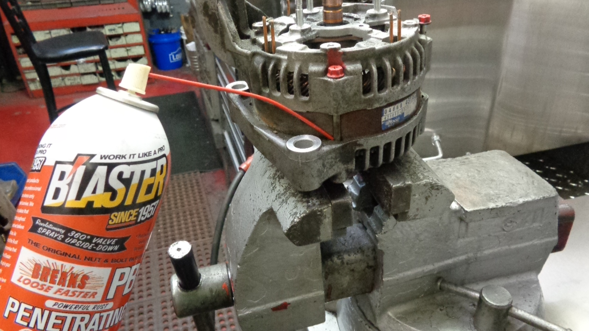
 Remove the 4 phillips head screws holding the terminal block, brush holder ass’y. Apply rust bust to the outside of the screws and allow ample time for penetration to work. With a small hammer, tap the head of the phillips screwdriver down into the screw before trying to break them loose. Moderate tapping pressure can be used on the 2 outer diameter screws, but caution should be used on the 2 inner most screws that fasten the brush holder to the terminal block. If desired, the 2 outer diameter screws can be removed first, then lift out both pieces together. (lift straight upward). Then, rust bust can be applied to the remaining 2 screws from underneath for better penetration. After penetration time has been allowed, support the underside of the screws with a ¼ “ extension while tapping the phillips screwdriver down into the screw. If you have trouble separating the terminal block from the brush holder, you can call us and order a new terminal block. They are not expensive.
================================================================================================================
REMOVAL OF RECTIFIER 
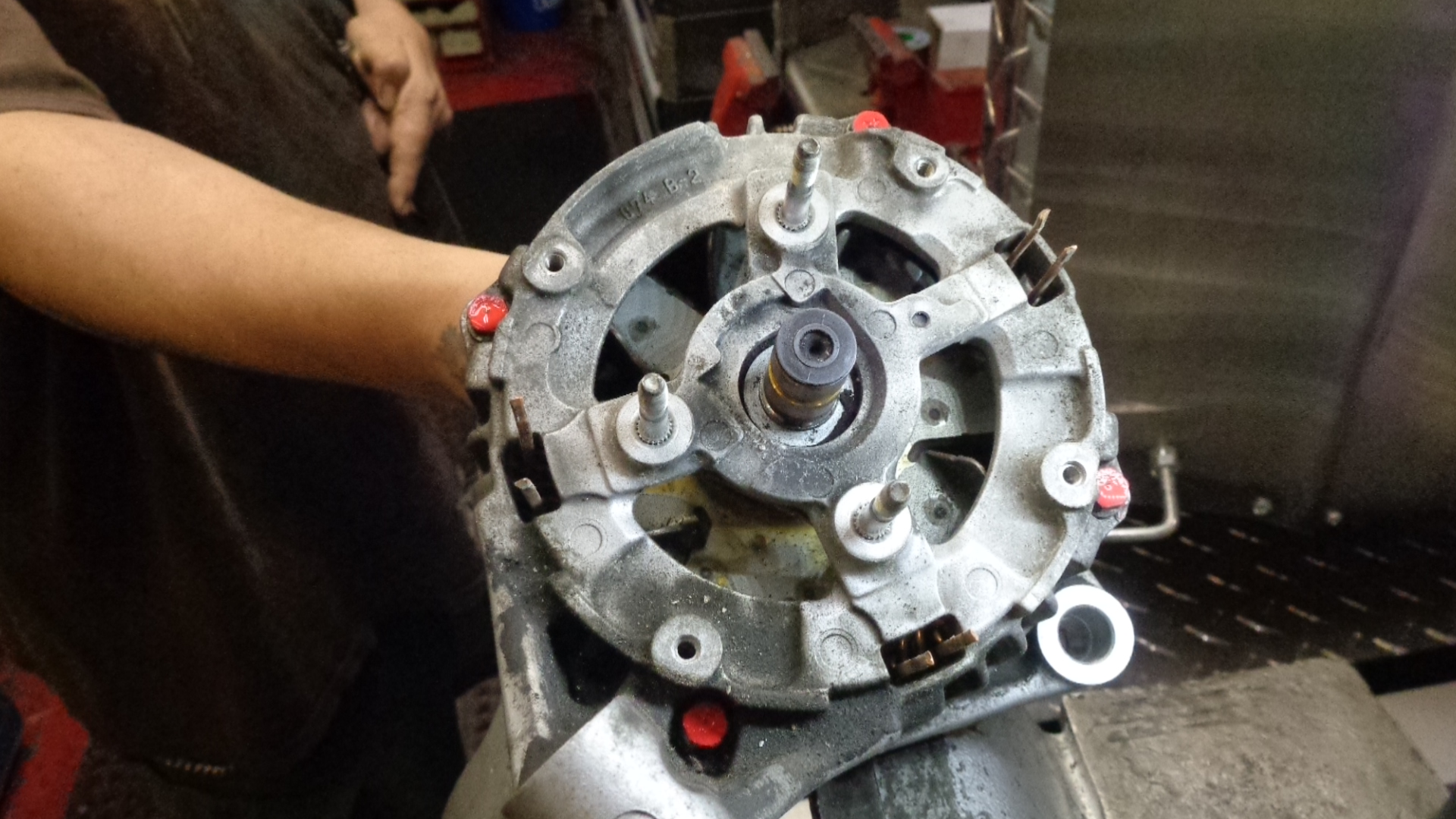
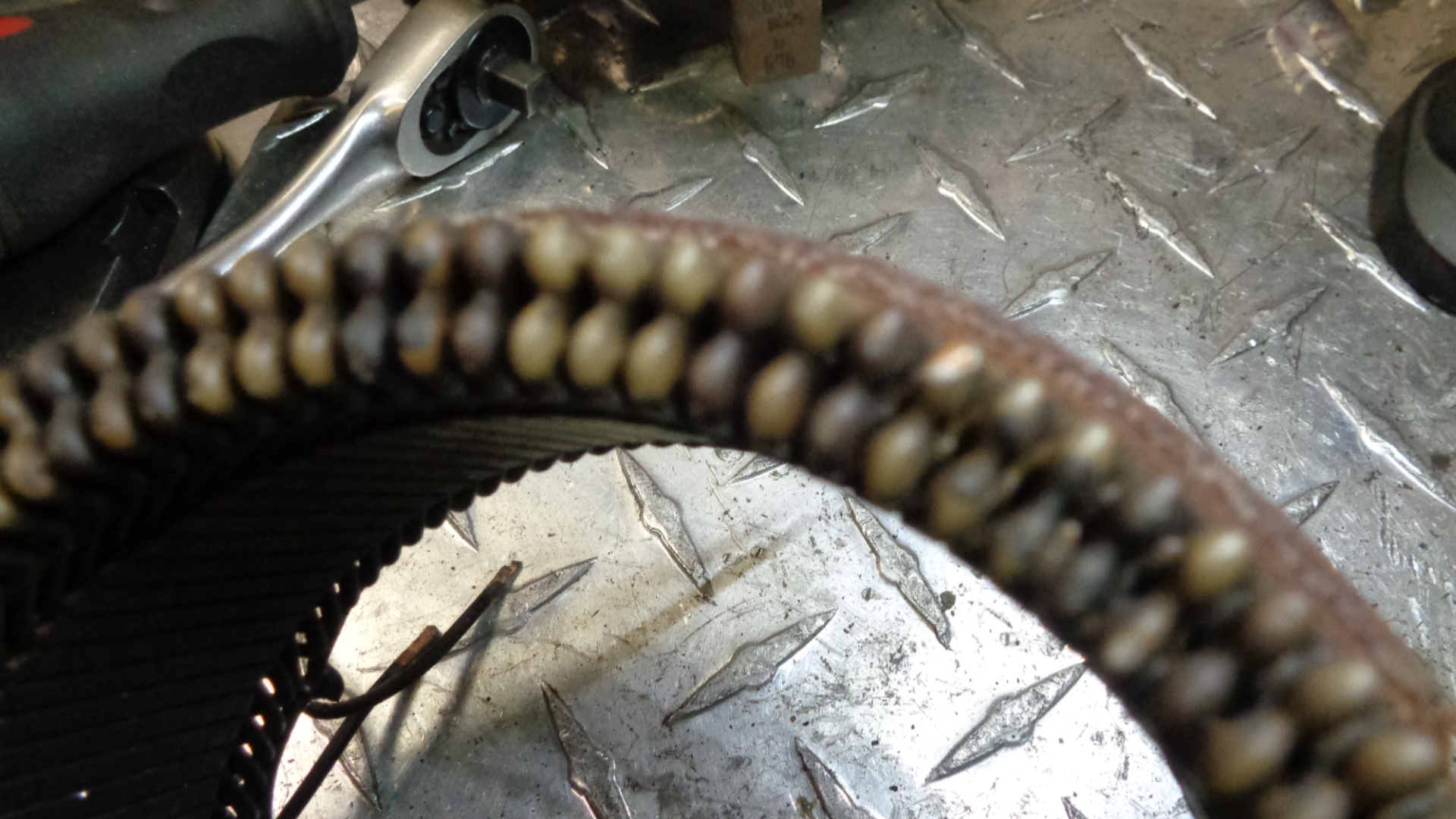
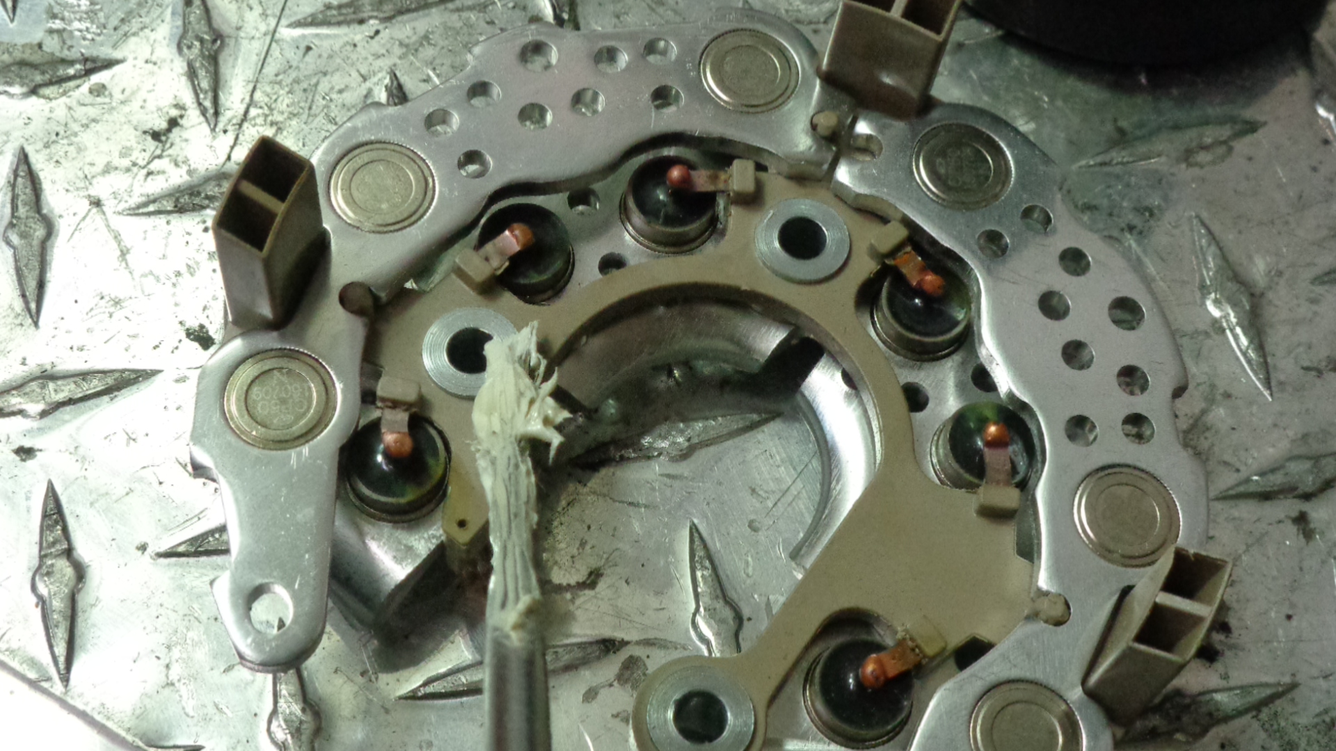
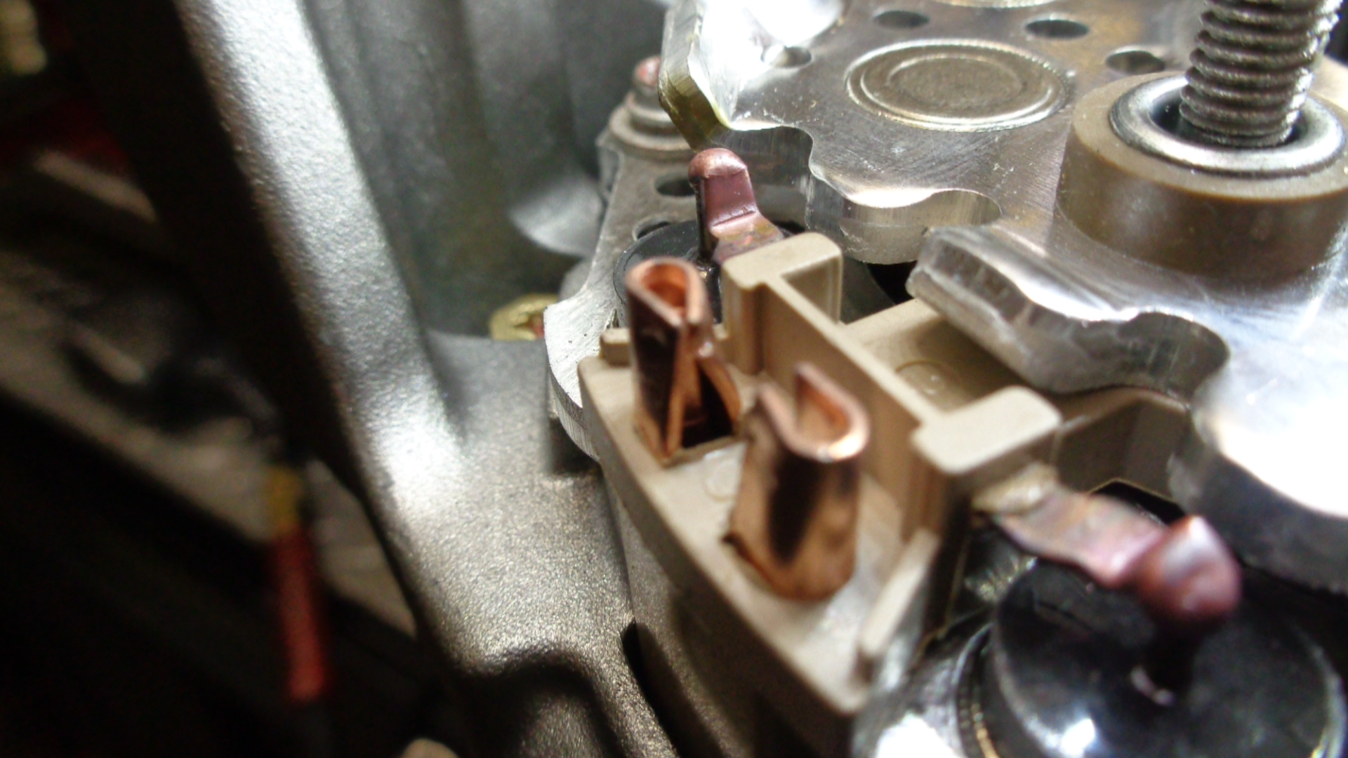
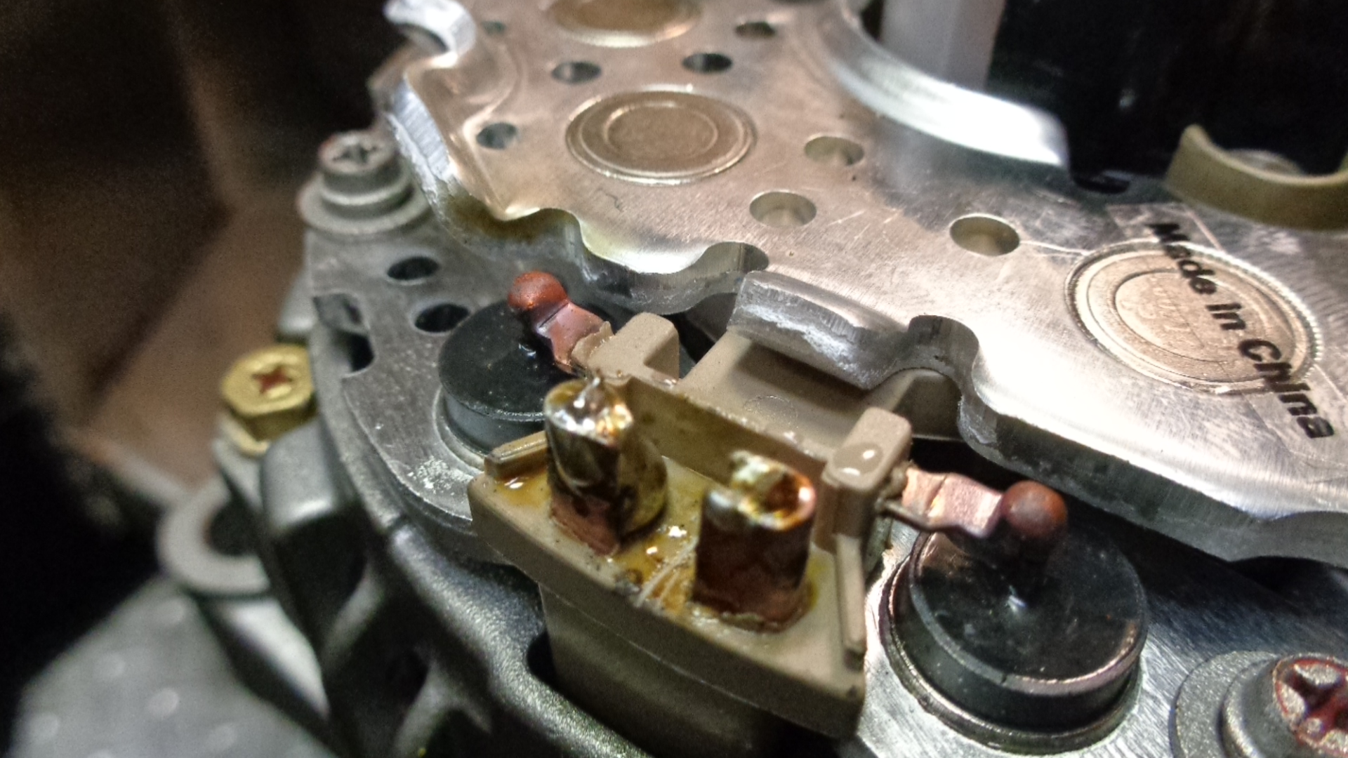
Find the 6 wires (3 groups of 2) that rise up thru the back plate and are mig welded to the rectifier. The globs of copper weld must be cut with a medium size pair of wire cutters at the highest point possible.


Then take a pocket screwdriver and dig the individual stator wires out of the old rectifier connector.
Please be mindful the idea is to end up with the longest stator wire as possible. The quality of the solder joint of the upcoming rebuild depends on the length of the wire you have to work with when you re-install the new rectifier.
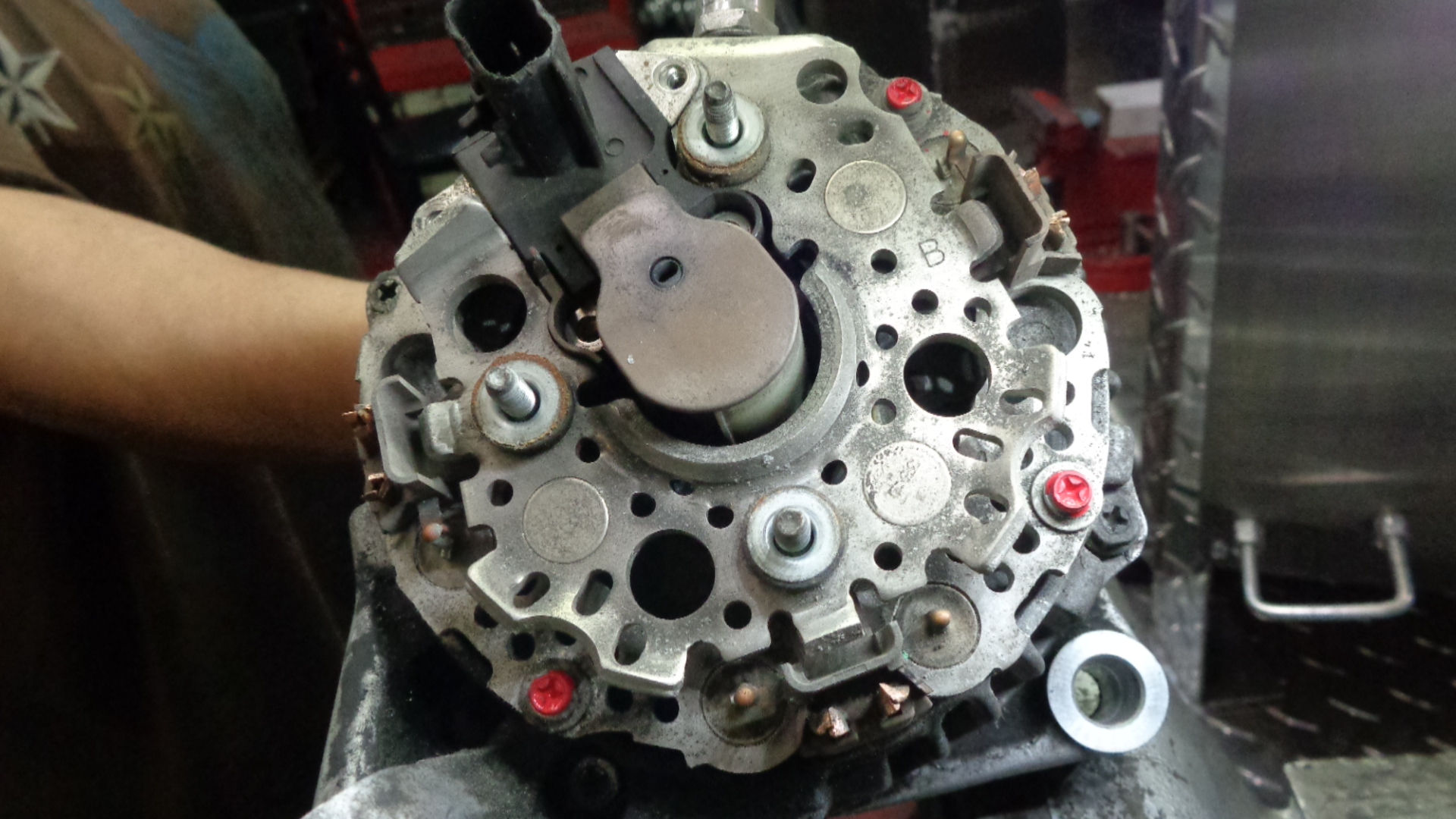
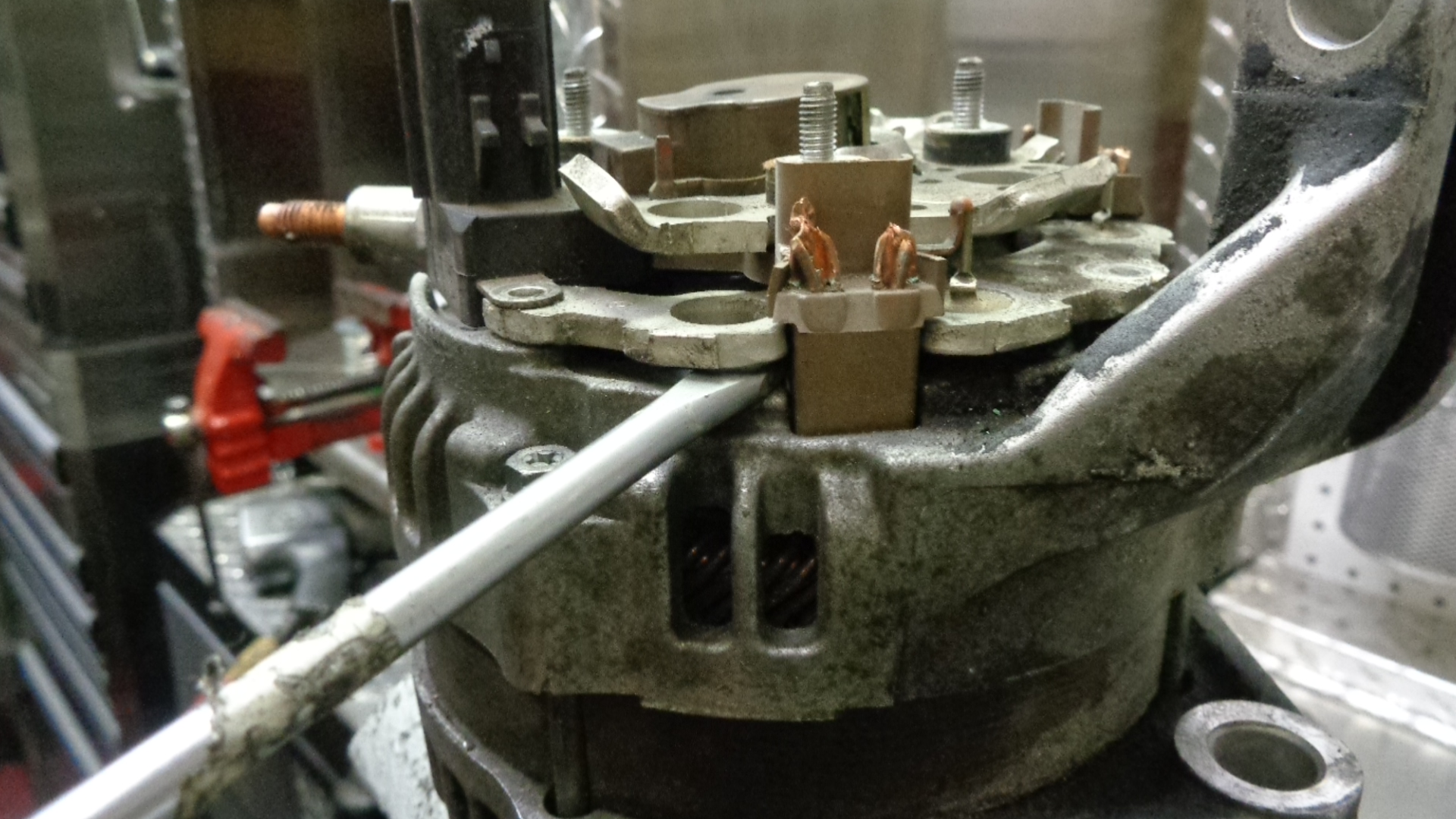
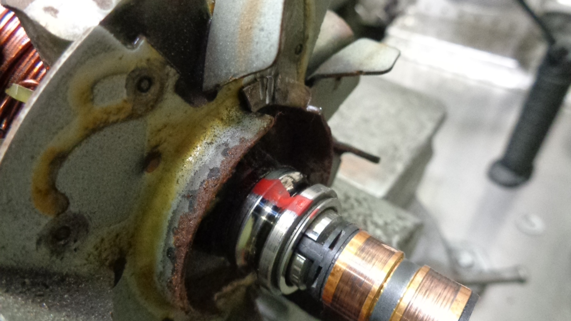
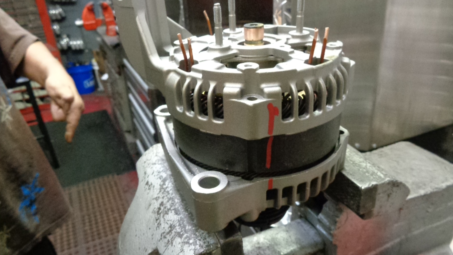
Find the three phillips head screws that hold down the rectifier. You can see them in the pic above highlighted with red paint. Tap a phillips screwdriver (with a small hammer) down into the x on the screws to get a good bite before you try to break them loose. Wedge a screwdriver between the rectifier and the back plate. Pry up on the rectifier to remove it from the alternator.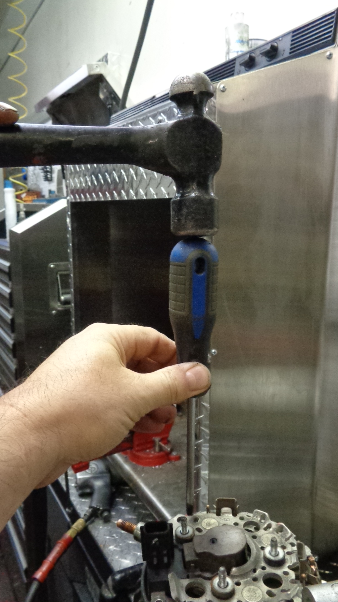
====================================================================================================
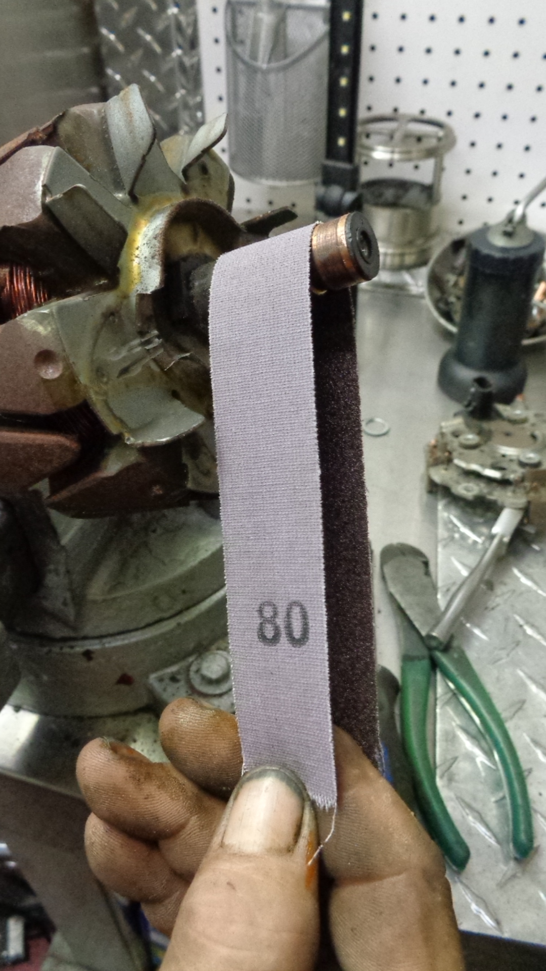
OBSERVE THE SLIP RING
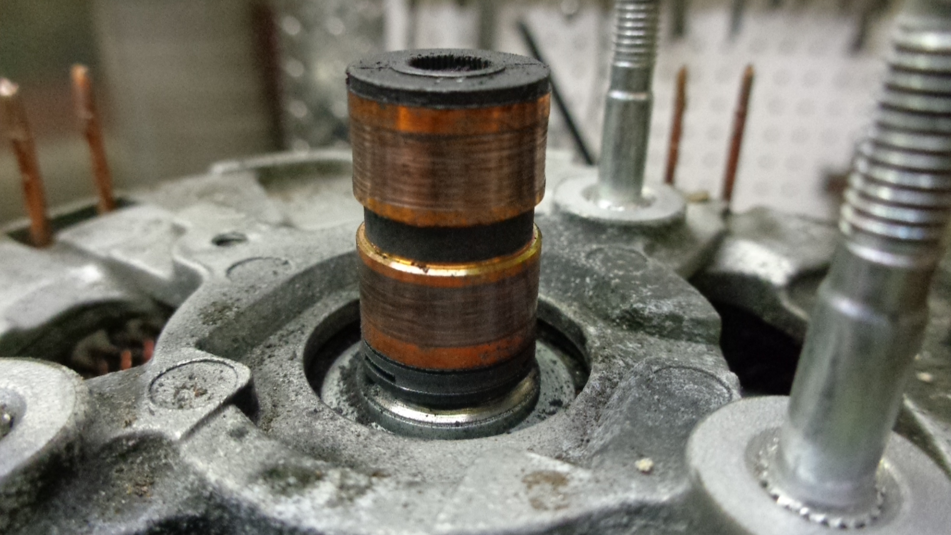
This slip ring should be polished with 80 grit, then finish with 120 emery cloth or medium scotch brite and re-used. For this vehicle, the wear exhibits normal conditions and decent battery condition during its duty life. 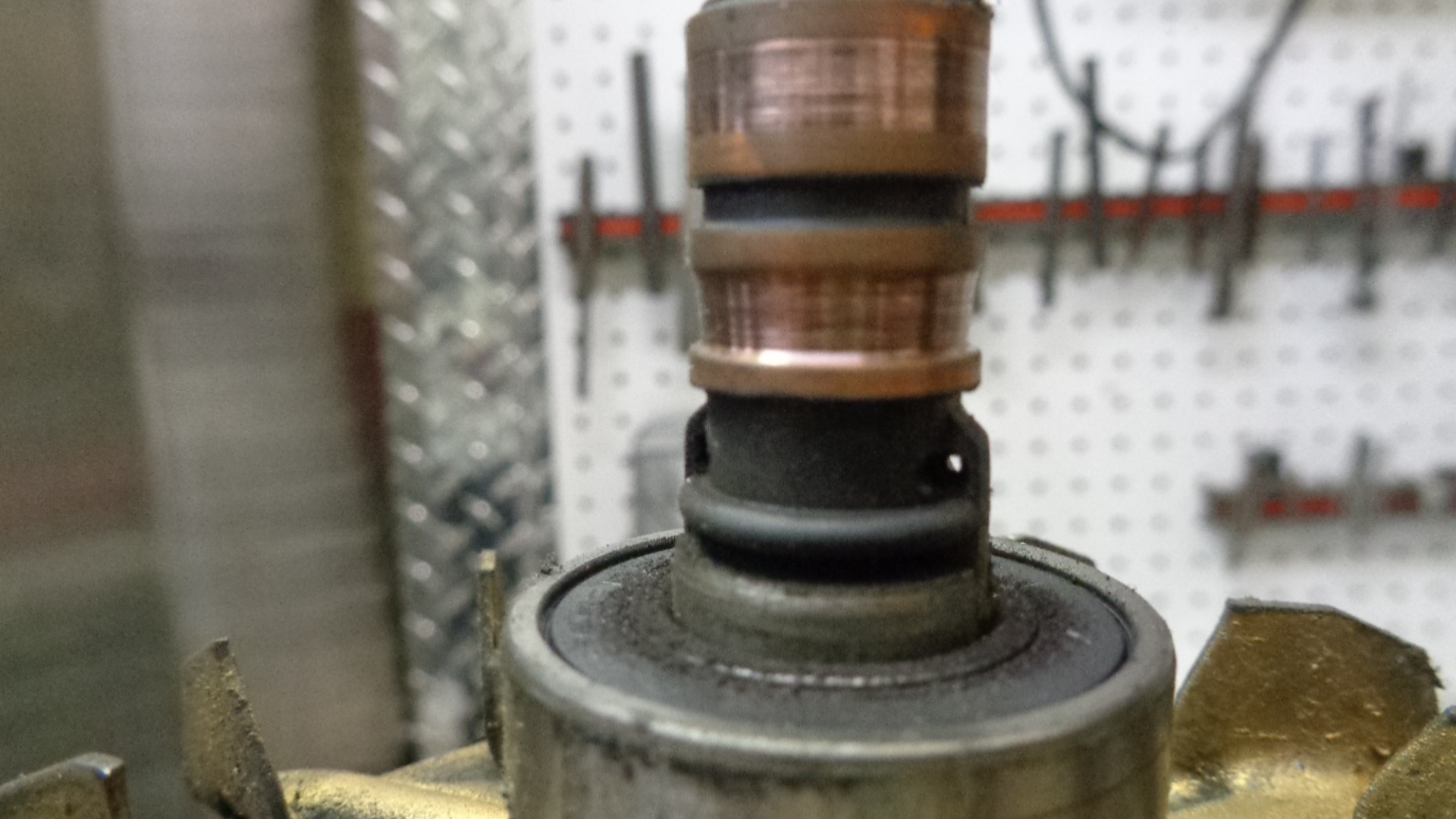
This slip ring is partially worn but not deep enough to be unusable. However, it should be noted to the rebuilder as a sign of an underachieving battery, defective wiring or grounds, or an over loaded electrical system. Finish with 120 grit strip of sandpaper or scotch brite medium.
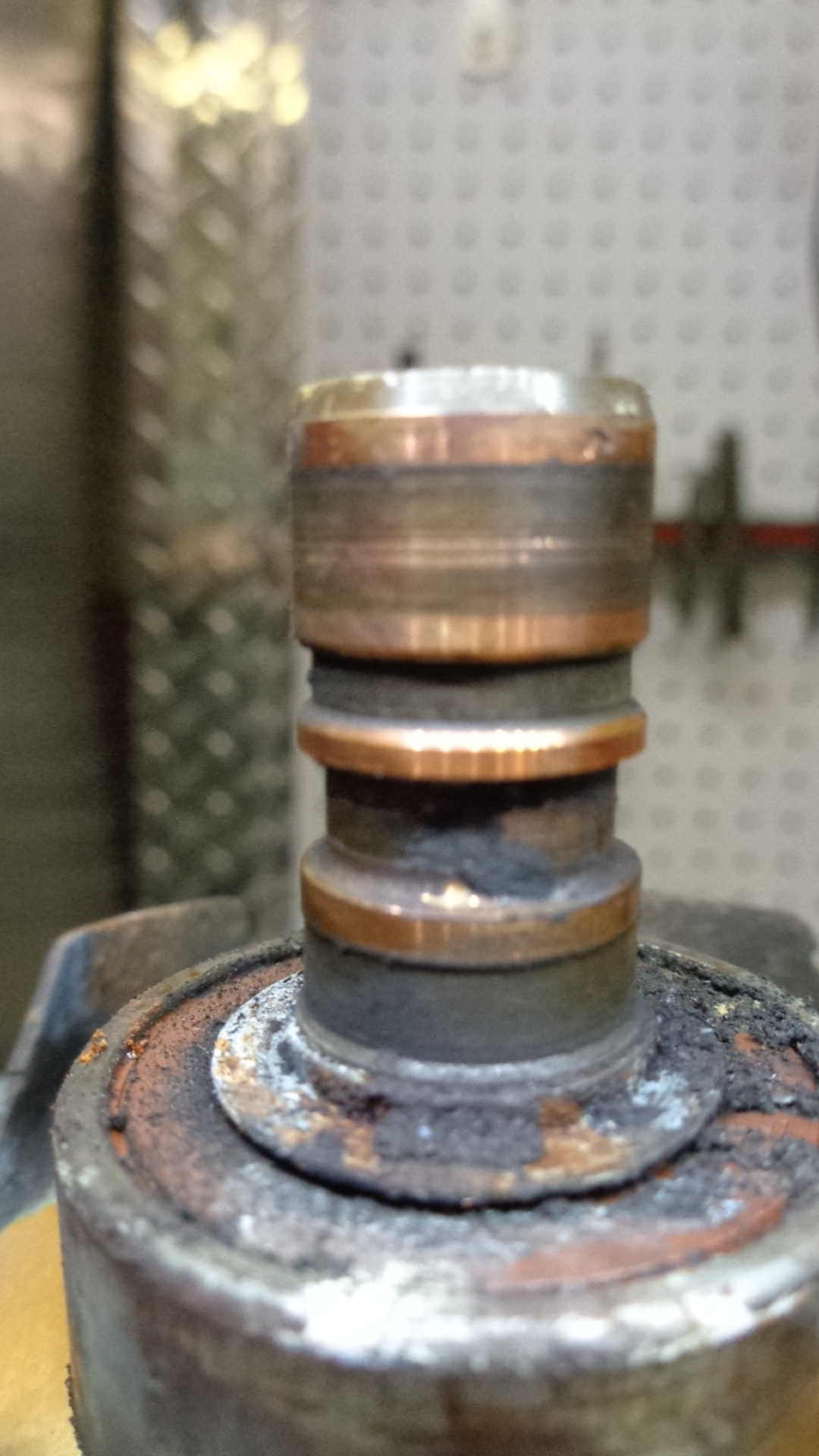
This slip ring would be considered unusable. The copper is worn completely through to the plastic and cannot be reconditioned. When the brush runs out of travel or loses spring tension an arc will occur which causes burning and facilitates further damage. Usually with Denso, this is not normal except for extremely high milage without service or exposure to pollutants such as oil or antifreeze.
==================================================================================================
BREAK THE ALTERNATOR APART.

Mark both plates with a paint stick or a center punch so they can easily be lined up again for re assembly.
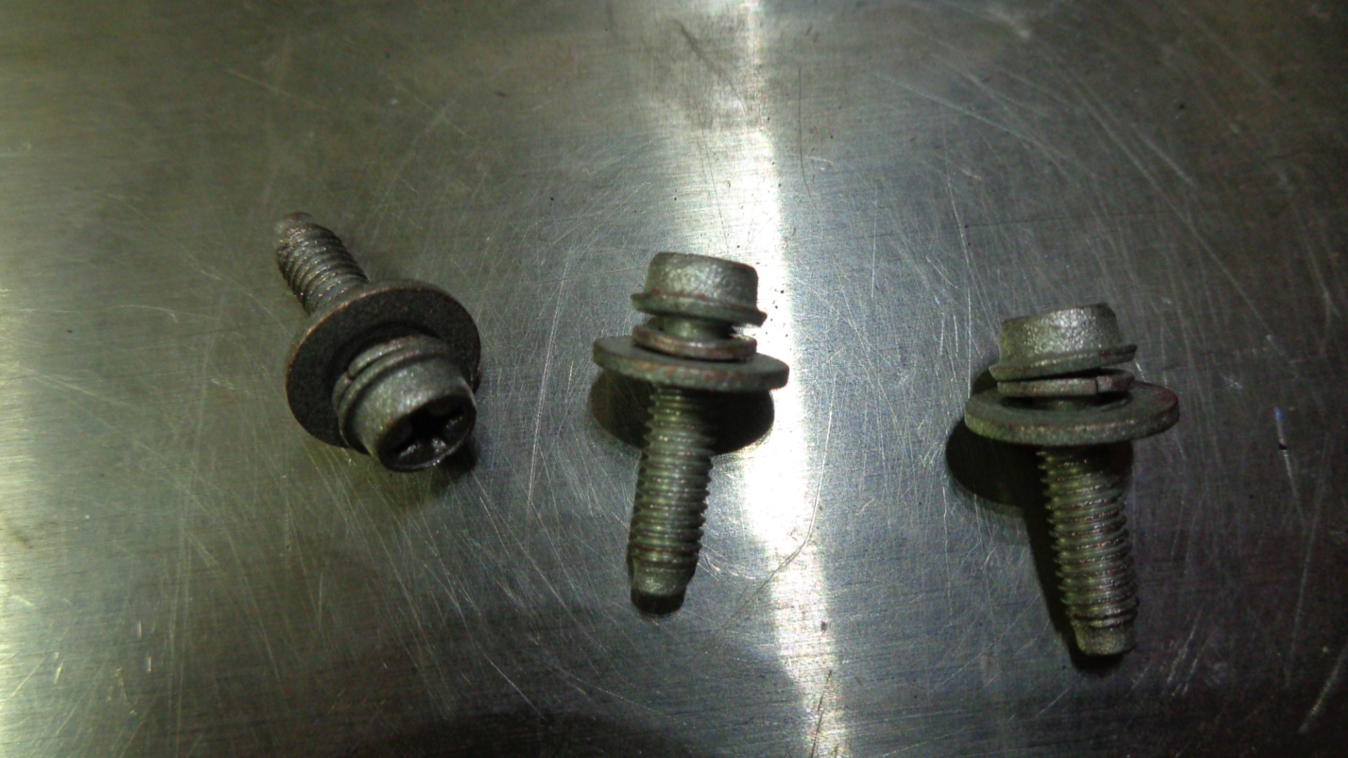
Find the the 4 bolts holding the 2 aluminum plates together. They are the 5/16” (8mm) head bolts near the outside diameter of the alternator. Soak them where they contact the aluminum with penetrating oil.
 Use a 5/16 deepwell socket and a ¼ inch ratchet to break them loose and remove them.
=========================================================================================================
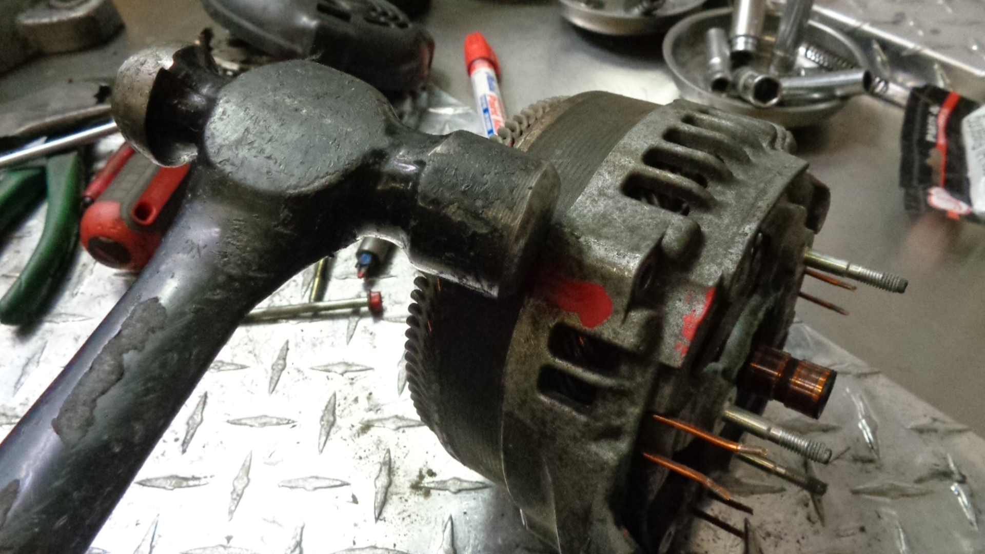
With a medium size ball peen hammer, tap briskly around the outside diameter of the alternator while turned on it’s side and laying on a bench or floor. Rotate tapping around the alternator’s complete circumference 3-4 revolutions.
Then begin to briskly tap the plates apart laterally, splitting the 2 aluminum plates apart on it’s axis. Hold the alternator firmly with one hand, then tap with the other.
Tap several times on one particular area, then tap 180 degrees from that point. Move around the outside circumference tapping in a certain area, then tapping 180 degrees from that point. Some penetrating oil may be used around the shaft and the bearings.
================================================================================
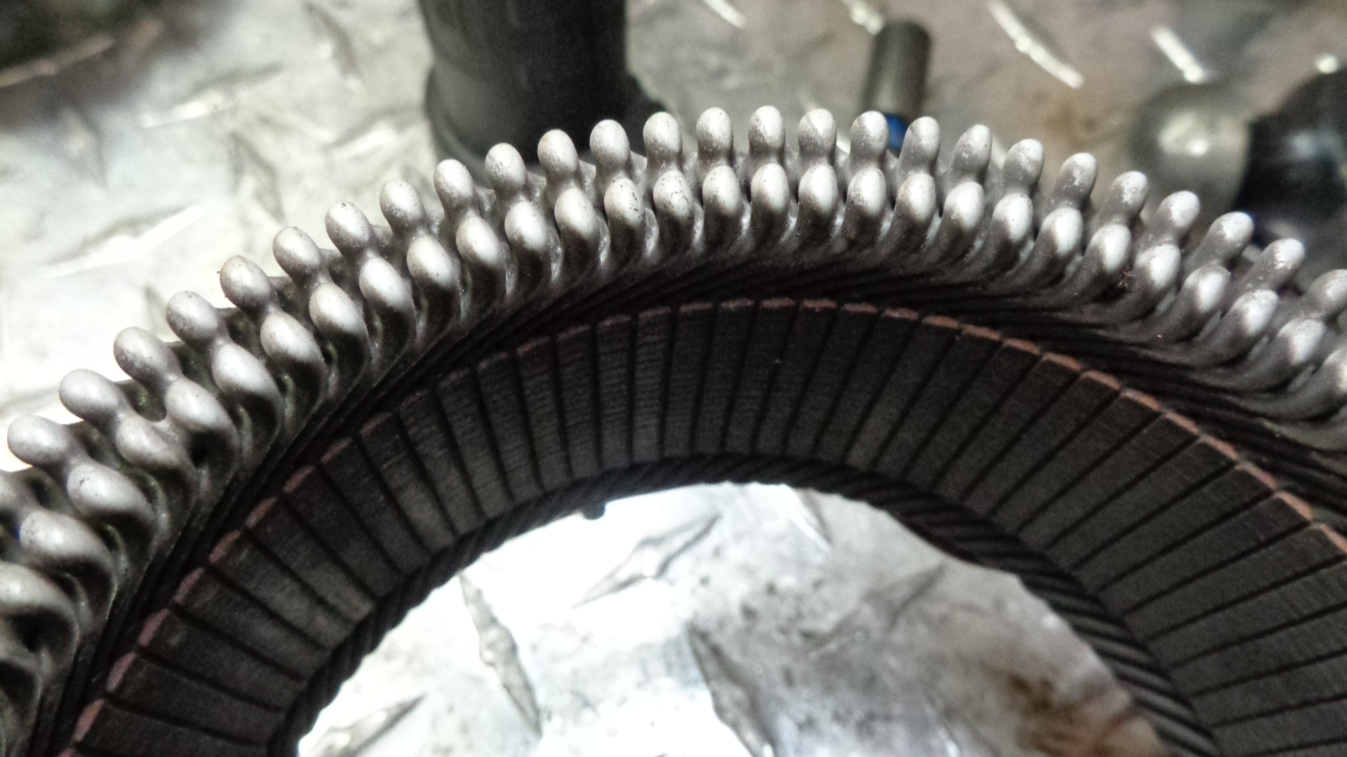
Most stators will look like this one. Notice how the windings are all a light uniform color and there is no burnt smell.
If you drove your car with bad diodes for a long time, it will ruin the stator windings and look like this. If you want to continue with the rebuild, you will need a new stator. Notice how some coils are darker than others and some of the plastic insulation is melted. Although all units should be inspected at this point, it is less than 5% that stators are unusable.
====================================================================================
 BEARING REMOVAL AND INSTALLATION
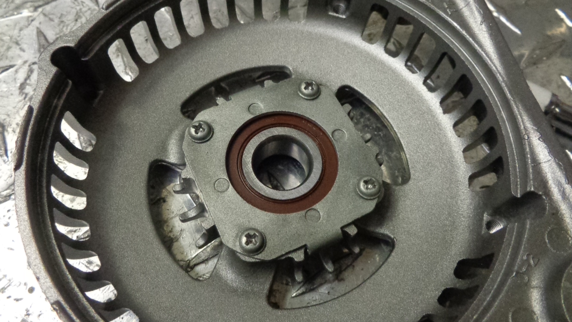
Pic of 4 screws and bearing cover installed. Apply penetrating oil to back side of hold down screws. With ball peen hammer, tap down briskly on heads of screws with bottom of plate supported on bench or cement floor to loosen threads. Tap phillips screwdriver or bit into screws. Remove screws and bearing cover.
 Flip drive end (DE) plate over and tap out bearing with a ¾” socket.
================================================================================
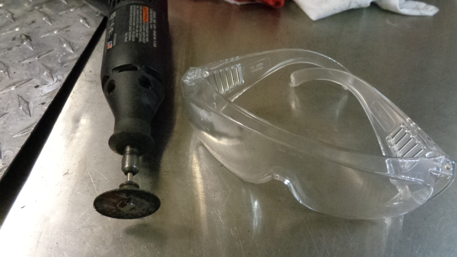 For the next step you will need a dremel with a reinforced cutoff wheel and safety eye protection.
Two things must be done to prepare the rear bearing for removal.
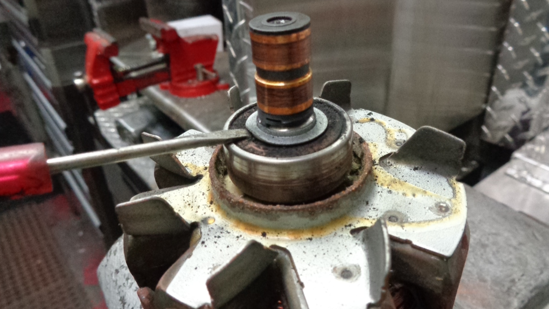
- Carfully 1. pry the tin shield up and out of the way with a pocket screwdriver. Discard shield as it will not be re used.
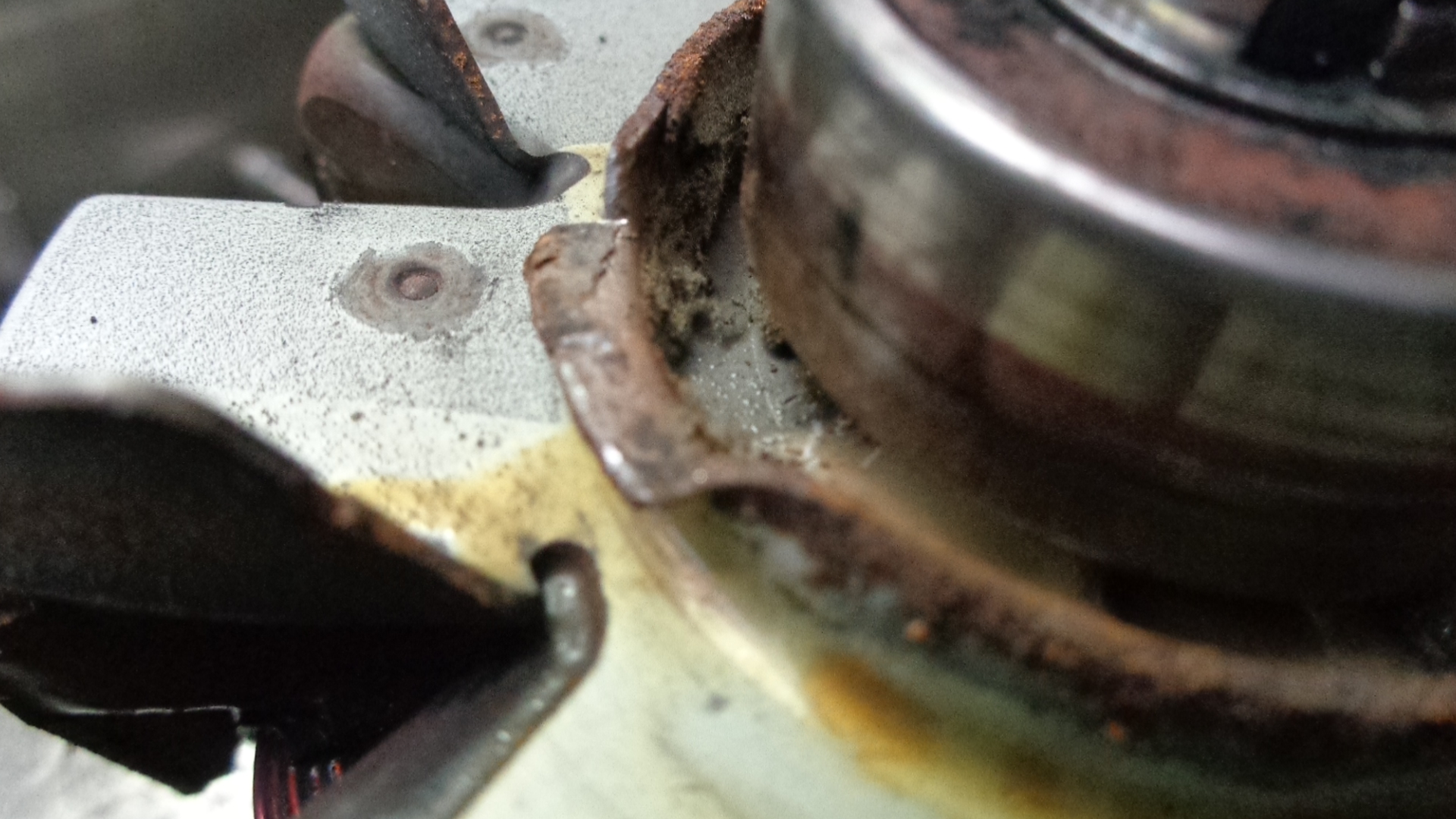
- Use regular size screwdriver to flatten out the dust ring, out of the way 2 places, 180 degrees apart.
After you have bent the lip down in 2 places you can use a bearing puller to pull the bearing off if you have one. It must be a 2 prong and have thin enough fingers to reach under the bearing where needed. You must be VERY cautious that the center piece does not deform the copper on the slip ring during this operation. Also, 2 large screwdrivers can be used to wedge between the rotor body and the bearing. Use 2 screwdrivers simultaneously and pry the bearing upwards from both sides. If this won’t work, use the dremmel method shown next.
===============================================================================================================
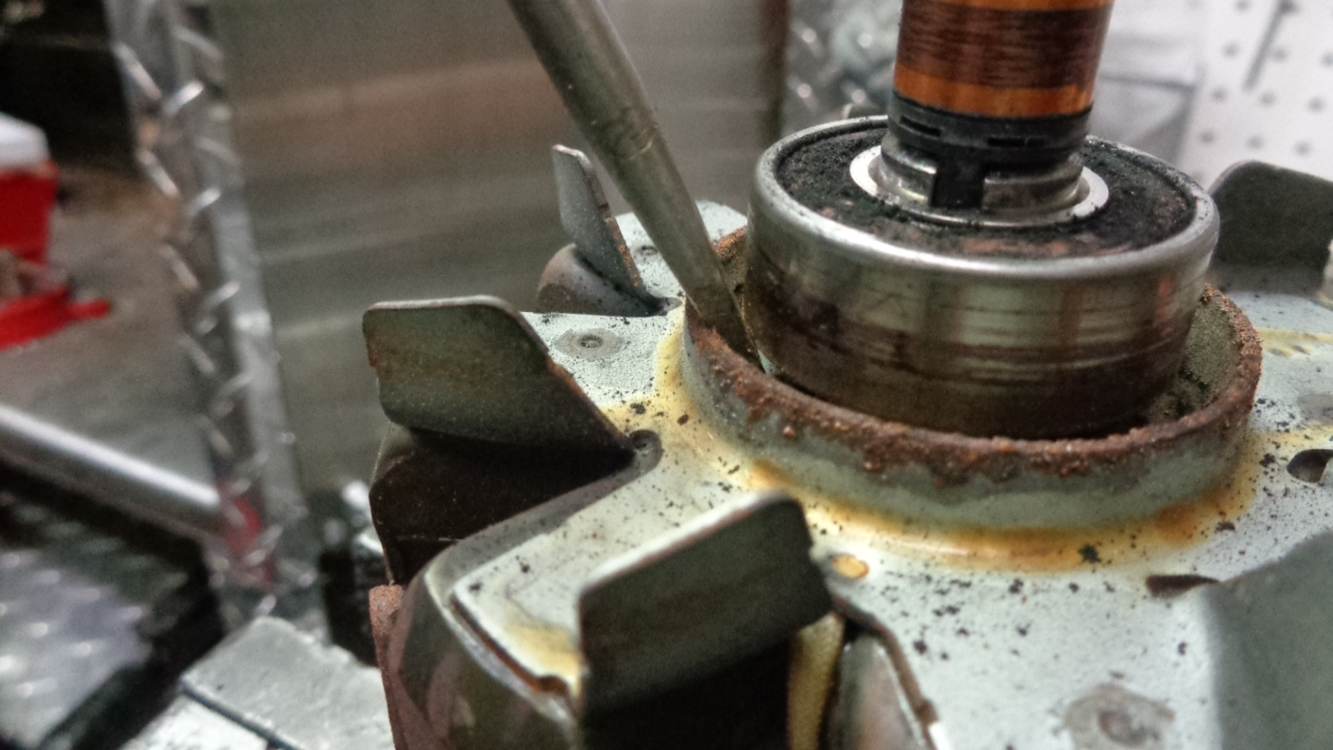
Make a cut with the Dremel tool where indicated by the red line. Use the flat part of the dust ring for room to complete the operation near the shaft.
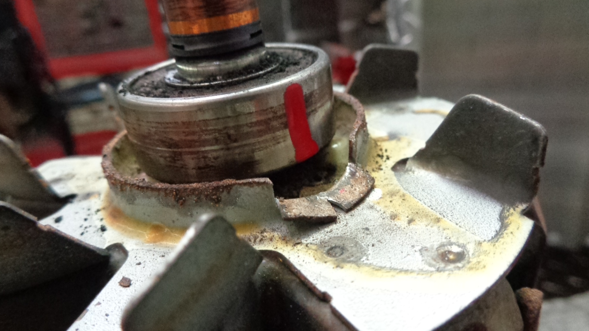
Make another cut identical to the previous cut, on the other side (180 degrees).


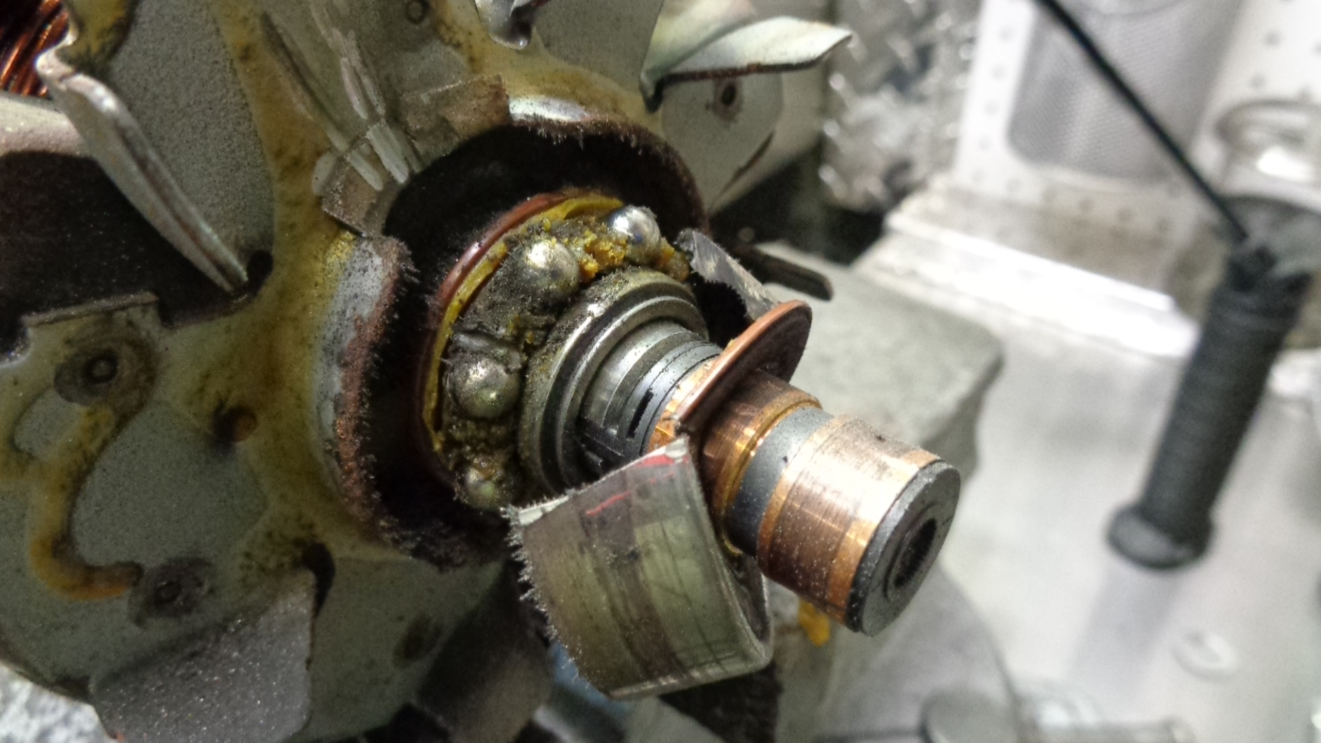
Remove outer race and balls and cage assembly.
=====================================================================================================
Use the dremel to cut the inner race from the shaft as well. 2 cuts (180 degrees apart) will probably be necessary. Do not be concerned with minor collateral damage to the shaft or dust shield as this operation is being performed. But, DO NOT allow any damage to the copper rings.
To minimize collateral damage to rotor and cutting time, the inner race need only by cut on the outside 80%. Then wedge the cut open with a screwdriver and the tightness will be relieved enough to take the inner race off easily.
===================================================================================================
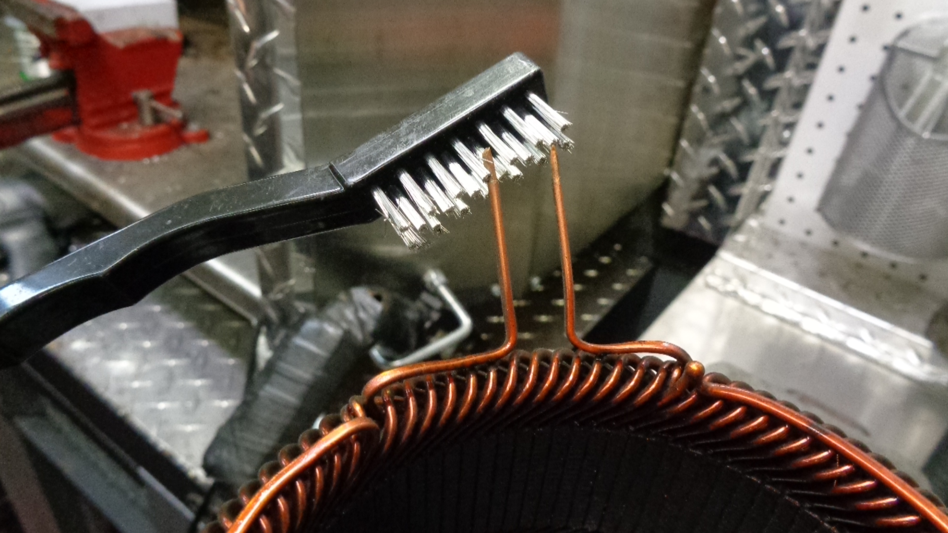
Meticulously clean the top ¾” of all 6 copper stator leads with a wire wheel on a bench grinder, a wire toothbrush, some 80 grit sandpaper or a sharp knife. Clean any rust or corrosion from the metal portions of the stator with a wire toothbrush. At this point, a spray paint or ignition sealer or red insulating paint can be applied to the metal portions of the stator ass’y to prevent future rust. Mask off the copper leads that were previously cleaned. 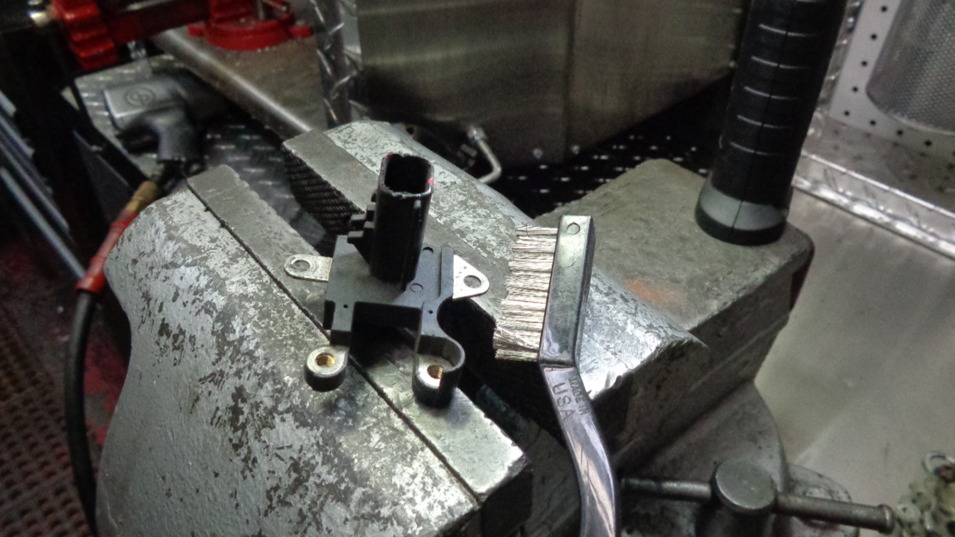
Also, with a wire toothbrush, scrub all the metal surfaces of the terminal block. Then apply dielectric or white lithium grease. Then, clean the 3 metal portions of the plastic cover with the wire toothbrush. Apply white lith.
=========================================================================================================
Use the wire toothbrush to scrub the shaft where the inner race of the front and rear bearings will go. Buff the entire shaft (both ends) with the wire toothbrush so the inner race of both bearings can easily be installed. Apply a very small amount of oil (¼-½ drop) of oil to the slip ring end of the rotor shaft and distribute it evenly around the entire surface area of the shaft. (avoid copper area)
========================================================================================================= 
Bake the front aluminum housing in an oven for 20 minutes at 300-350 degrees F. The bearing may go in easier if in the freezer for 20 min or longer. Lace the outside race of the bearing with red loctite. Drop the bearing in, tap in lightly on outer race if needed. Install the bearing cover and the 4 screws. A few drops of red loctite on the rotor shaft is an option but not necessary. If you do, keep the oil away from the loctite.
Set the front plate face up in a vise and push the rotor in the center hole. Place rear bearing over slip ring and get it started on the shaft. Get an 11/16 deepwell socket. Make sure the socket head contacts the inner race of the bearing but does not contact the rubber seal. Tap the bearing down onto the shaft but NOT all the way down.

INSTALL REAR BEARING
Place a drop of oil on shaft where back bearing inner race will be installed.Make sure FIRST that inside of deepwell does not contact copper portion of slip ring. Use 15mm deep to tap rear bearing on slip ring end shaft.

Leave approx ⅛ “ steel shaft showing, above and below bearing.
Place rotor/ front plate ass’y in vise. Snugly, but do not tighten completely. Thread pulley onto shaft by hand.
With 17mm hex head and ½” drive impact, bump the pulley tighter a few quick times. Spin pulley while holding front plate to make sure no alternator rotor fins are hitting the front plate.
Snap in the dust cover of the pulley.
===========================================================================================================
Use wire toothbrush to clean any corrosion on the circular portion of the both aluminum plates (where the stator sets). Apply a thin layer of white lith grease or dielectric grease.
Set back plate on stator with 6 wires coming up thru the 6 rectangular holes. Align grooves in outer diameter of stator with bolt holes in back plate. Lace the rear plate bearing hole with a few drops of oil and spread around with finger.
Set the 2 pieces on the rotor ass’y mindful of the previously placed alignment marks. Set front plate on vise so pulley is not stressed. With a ball peen hammer, tap around the entire surface of the back plate to install into position. Start tapping mostly towards the center, moving in 180 degree increments. As the plates begin to bottom out, tap on the front plate (bottom) to align bolt holes with grooves in stator.
When plates are close enough to get through bolts started, place a generous amount of grease on the threads of all 4 bolts. Start all 4 bolts and alternately thread together while periodically tapping near center of rear bearing.
After assembly is complete, hold alternator in palm of one hand, spin pulley with other hand. Make sure rotor spins freely. Tap a few more times around bearing vicinity and snug up the bolts.
===========================================================================================================
Place a thin layer of white lithium grease on 3 spots on bottom of new rectifier. Set rectifier on alternator with wires through 3 slots and 3 mounting studs aligned.
Install 3 rectifier hold down screws. Wait for longer one at the top until brush holder terminal block installation.
Install terminal block with longer phillips head screw where indicated. Install brush holder ass’y with screws.
===========================================================================================================
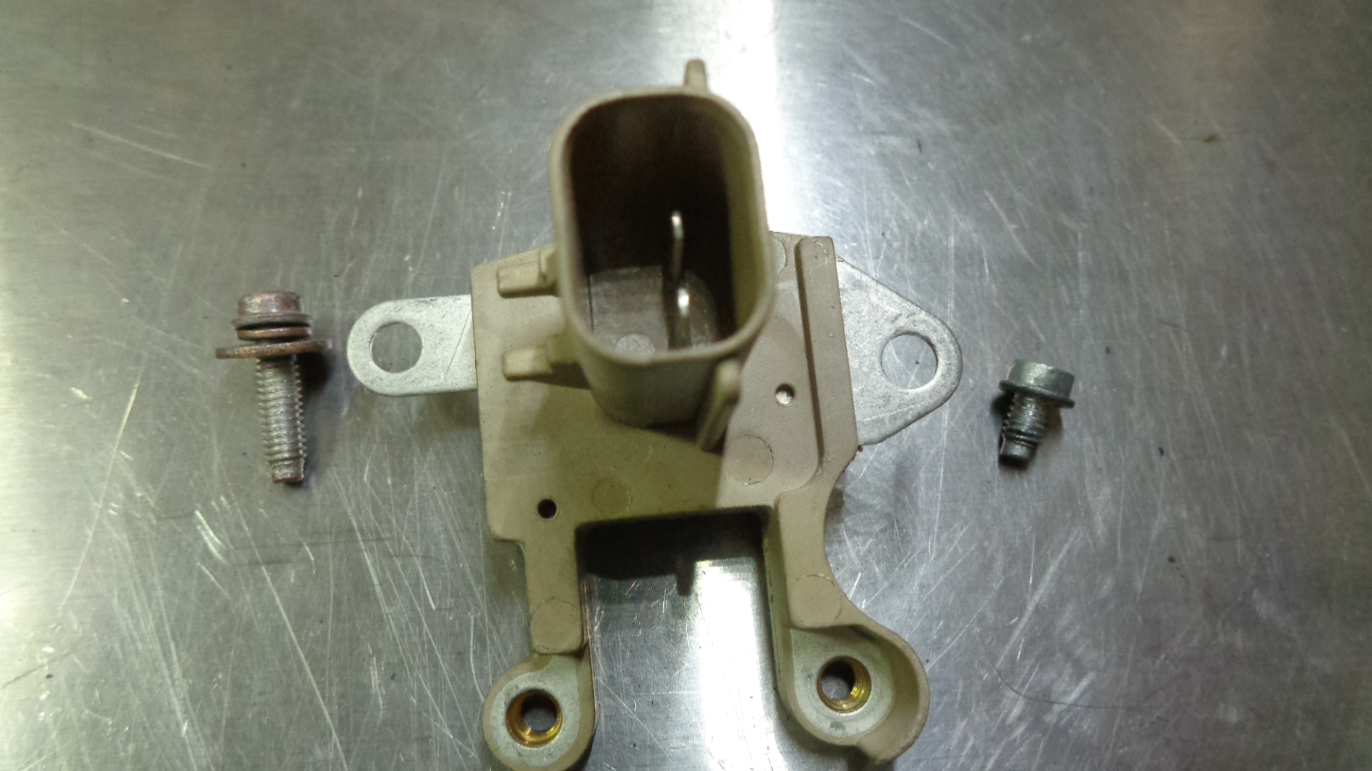
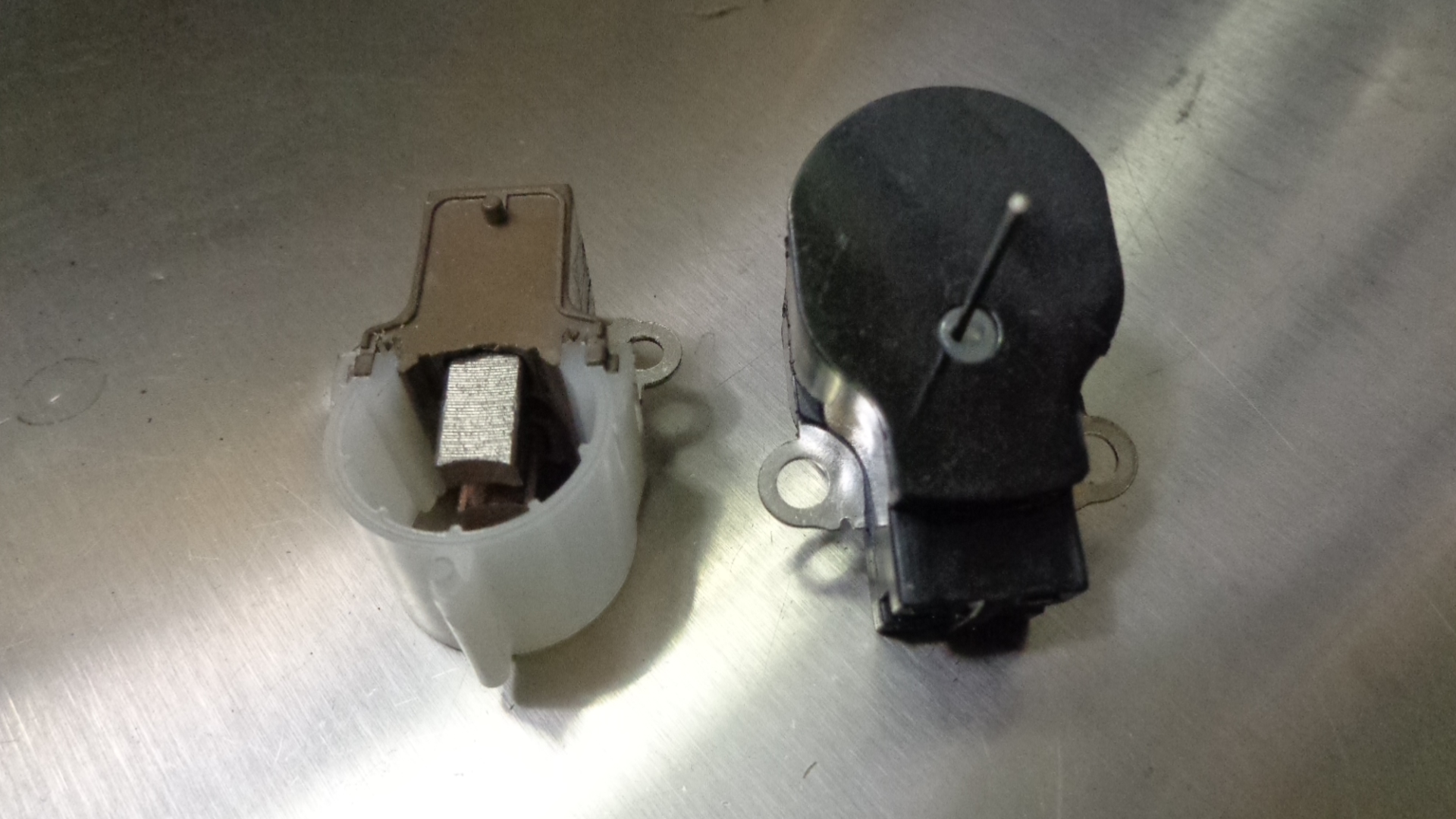
There are 2 different styles of brush holders. Match the one you have for your app. Keep the other one or discard.
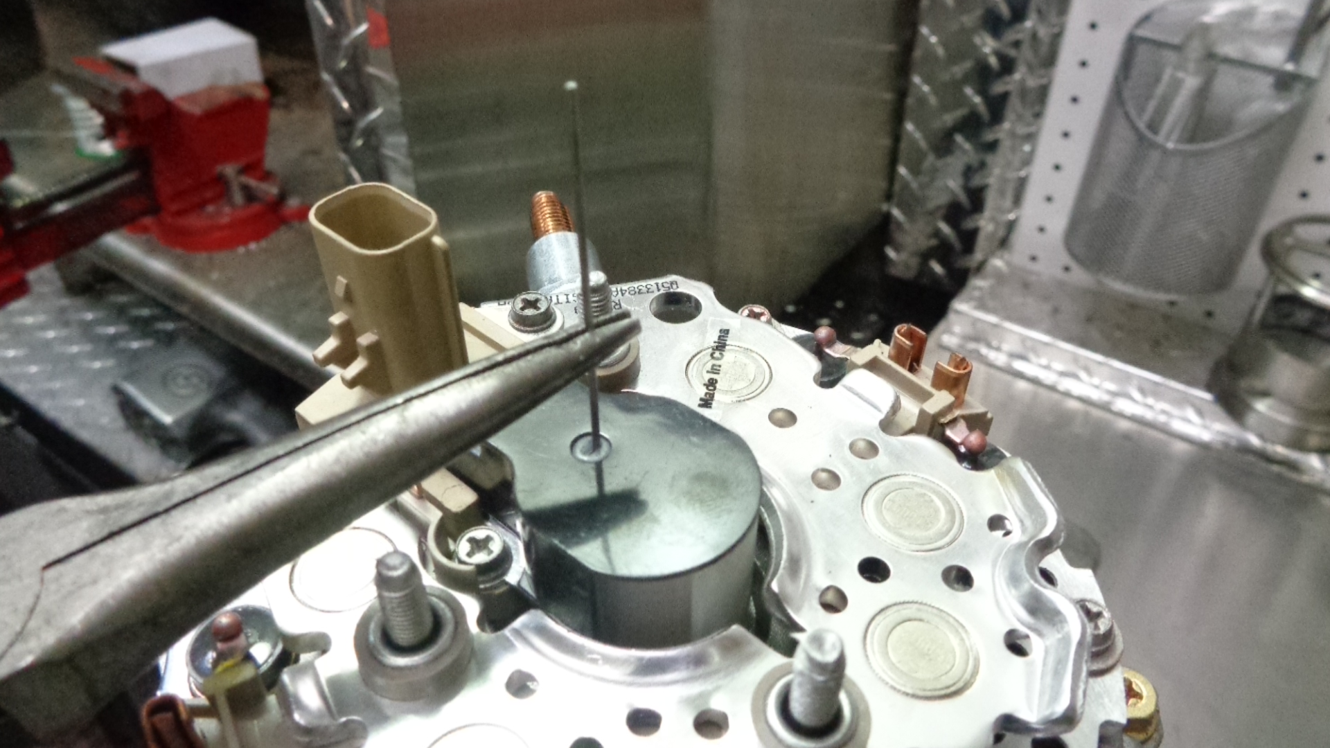
Pull pin semi slowly, listen for 2 clicks as brushes spring to rotor.
===========================================================================================================
Use a pocket screwdriver to press copper stator lead wire into back of rectifier solder terminal.

======================================================================================================
Crimp firmly. Form a tube around stator lead with needle nose pliers.
Fill tube with melted solder. Use at least a 200W soldering tool and 70-30 or 60-40 rosin core solder. Repeat for all stator lead connections. Make sure solder completely liquifies but does not bleed across to other connection.
==========================================================================================================
Check tightness of 4 bolts with 5/16” (8mm) heads that hold alternator together. Check 4 phillips head screws that hold brushes and terminal block down. Check 3 phillips head screws that hold rectifier down.
============================================================================================================

Place battery post insulator on battery post flat side towards middle of alternator.
=========================================================================================================
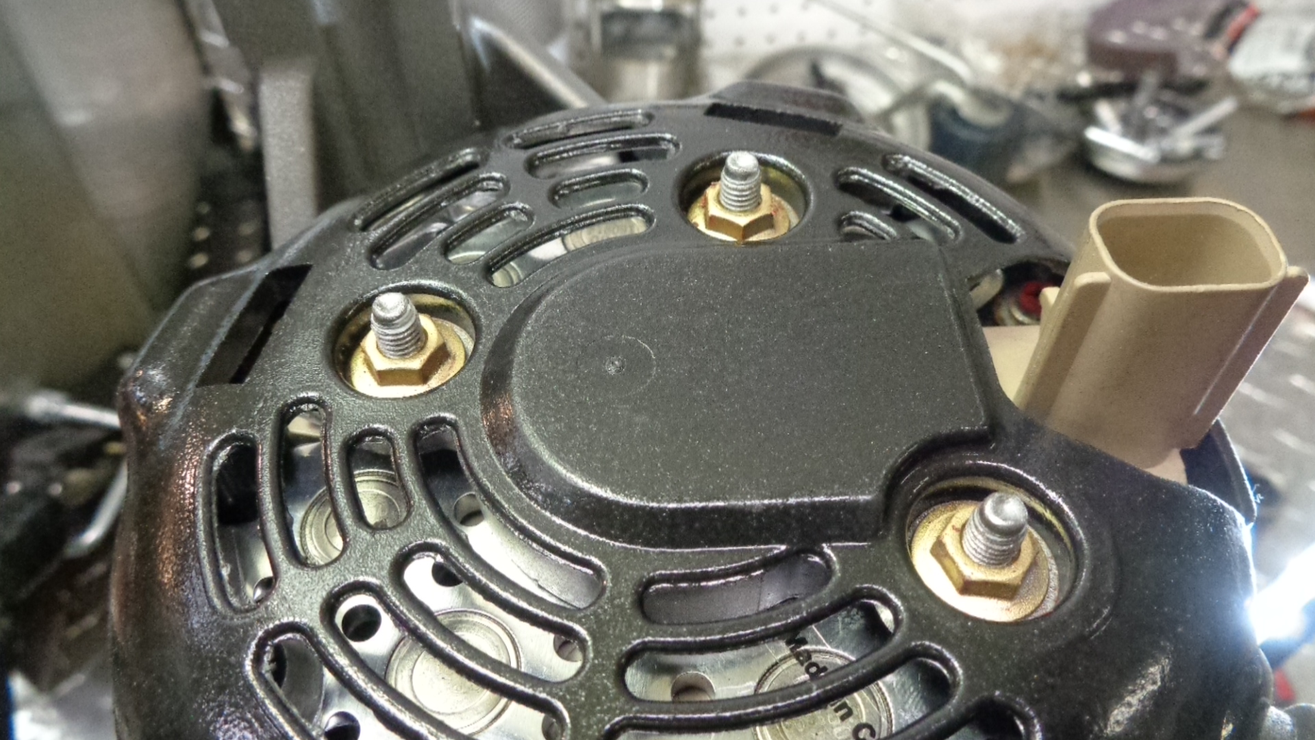
Place cover on 3 posts. Install 3 nuts, tighten.