VOLTAGE REGULATOR
VOLTAGE REGULATOR DEFINITION
The following is a definition and explanation of the basic functions of the most popular domestic voltage regulators in the US automotive market in a timeline order that they were implemented. A voltage regulator is nothing more than a device that maintains a predetermined voltage in any electrical system. It’s function is to monitor system voltage variances, due to various vehicle loads and adjust the charging device to a set voltage.
_________________________________________________________________________________________________________
CUT OUT
The cut out was one of the first voltage regulators on very early 6 volt cars and farm tractors. It was used in conjunction with a generator type, that had a third adjustable brush. The third brush was set to the desired amperage output. When the generator energized, the points in the cut out were electro magnetically pulled in. As the vehicle voltage rose to a high set point (7.5VDC for example) the cut out shut off (thus the name cut out). The vehicle would then run on battery voltage until the low setting was reached, then the cut out would turn the generator back on.
Cut outs only had a single coil and appeared to be about the size of a horn relay because, in fact, the internal winding and points appeared very similar to a horn relay. Now, we consider this system to be crude and basic. The system was constantly charging and discharging, which could be noticed in the lighting systems and the gauges. And yet, the simplicity of the era is still reproduced to this day by nostalgic farm tractor collectors and considered by many to be quaint.
________________________________________________________________________________________________________
MECHANICAL VOLTAGE REGULATORS
Then, as 12 volt systems began to appear, and even in later 6 volt systems, the mechanical voltage regulator became more and more popular. This was an improvement over the cut out because the mechanical voltage regulator had the ability to maintain a relatively smooth voltage, rather than constant charge/discharge. They did this with 2 electromagnetic coils : One heavily wound, thick wire coil to regulate current, and one coil with much thinner wire and many more rotations to regulate voltage.
By monitoring and adjusting the current, as well as the voltage, an overall consistency was achieved that was much more desirable for performance. Even with the advent of affordable silicone and diode doping procedures in the early 1960’s, which brought the first alternators, the mechanical voltage regulator remained the servant of the 12 volt automotive and farm electrical systems for approximately a decade.
________________________________________________________________________________________________________
ELECTRONIC VOLTAGE REGULATORS
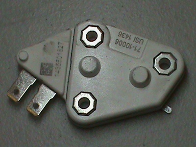
Electronic “built in” the alternator voltage regulators were first introduced in the US by a General Motors sub company called Delco Remy in the early 1970’s. The “SI” series which stood for series integral was considered one of the most revolutionary charging system inventions of it’s time. The infamous 10SI was most popular in 37, 42 and 63 amp versions, depending if vehicles were equipped with air condition or not. The regulator’s job was 3 fold.
- monitor vehicle voltage
- vary the field circuit to control alternator amperage output
- in conjunction with the diode trio, put out the idiot light
Ford, Chrysler and other manufacturers also transitioned to electronic voltage regulators for their uncanny ability to produce a consistent, even system voltage, but the location remained separate from the alternator itself.
_________________________________________________________________________________________________________
COMPUTER CHIPS IN VOLT REGS.
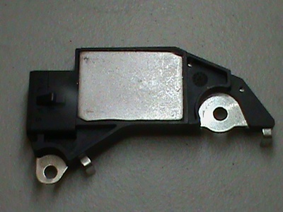
By the late 80’s, the integration of the computer chip type technology found it’s way to mass production in voltage regulators. The Delco Remy CS130 series (charging system with 130mm stator) was in full scale production in all GM vehicles. The most popular regulators were OEM marked 411 and 408. The CS regulators proved be extremely hardy and versatile. They were also much smarter and faster than the transistors and had the ability to compensate charging voltages with variable ambient temperatures. In other words : they could charge more in the winter and then less in the summer.
The original CS series alternator had several problems. The original design wafer style avalanche diodes did extremely bad in the heat. Also the rear roller bearing was extremely small, and had to be able to move laterally as the shaft thermo cycled. (A definite downgrade from it’s earlier needle bearing predecessor). Many CS130 series alternators failed at 60K when the manufacturer warranties had expired.
In an “ill gotten” attempt to thwart aftermarket competition, GM proclaimed the CS130 alternator to be non- rebuildable and even published factory technical service bulletins that solicited the CS130 to be a “disposable” . Many aftermarket rebuilders across the US considered this to be an attack on the aftermarket electrical business. But the CS series WAS rebuildable, and instead of ruining the aftermarket rebuild business, it became a huge money maker for all electrical rebuilders in North America. This just goes to show you…You can’t believe everything you read, even if it’s a factory TSB.
_________________________________________________________________________________________________________
CS130D SERIES

After GM disassociated itself with Delco Remy, a UK company “Delphi” got the job in the middle 90’s. With the new 130D series (the D stands for dual cooling fan) many of the diode and bearing flaws of the CS130 series were corrected. The regulators were technologically similar and had a section of cooling fins. Many were marked 702 and 705 depending on the wiring harness application. They also had a similar 4 pin plug that had variable uses if needed like diagnostic computer feed or tachometer output.
_________________________________________________________________________________________________________
RVC

Regulated voltage control can be found on vehicles around the middle 2000’s. The computer decides what the proper charging voltage should be, based on informational inputs and pre designed programming, then tells the voltage regulator what voltage to set. There are 3 basic reasons for this mindset. 1. Better fuel economy. 2. Increase battery life expectancy. 3. Increase electrical component life expectancy.
RVC systems and their counterparts in Ford (Visteon) and Chrysler ( regulator in in the computer) utilize either the BCM (body control module) or the ECM (electronic control module) or both. Many computer controlled regulators are capable of various voltage levels, increase idle speed commands, and a systematic load shedding function during limp mode. The computer can call up different modes of operation such as windshield de-ice, fuel economy, or even a sulfated battery.